

Description
ABB TINT-4331 Drive Board Introduction
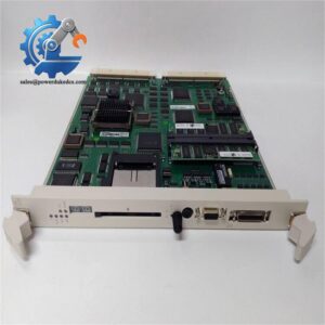
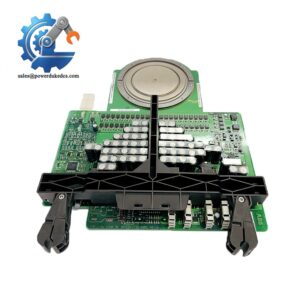
The ABB TINT-4331 functions as an internal gate driver and power supply board for ACS580 variable frequency drives. It routes 24 V control power and fires the switching modules to modulate output frequency. When an ACS580-046A-4 drops offline with a fatal power stage fault, getting the motor spinning again dictates your entire shift.
Swapping this specific PCB cuts troubleshooting downtime to under 45 minutes. Relying on an exact-match replacement prevents the need for a complete $4,000 chassis swap. Bottom line — it works. Just verify your exact frame size and firmware revision before installation.
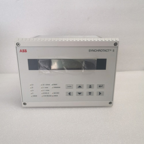
ABB TINT-4331
Key Technical Specifications for 3AXD50000
| Parameter | Value |
| Component Category | Inverter Power Supply / Gate Driver PCB |
| OEM Internal Designation | 3AXD50000 |
| Compatible Drive Series | ACS580 |
| Target Frame Size | R3 / R4 (specifically 046A ratings) |
| Operating Temperature | −15 to +50 °C |
| Control Power Input | 24 V DC (Internal Bus) |
| Mains Voltage Rating | 380 to 480 V AC, 3-Phase |
| Communication Interface | Internal ribbon header to CCU |
| Cooling Method | Chassis heatsink forced air |
| Status Indication | Surface-mount diagnostic LEDs |
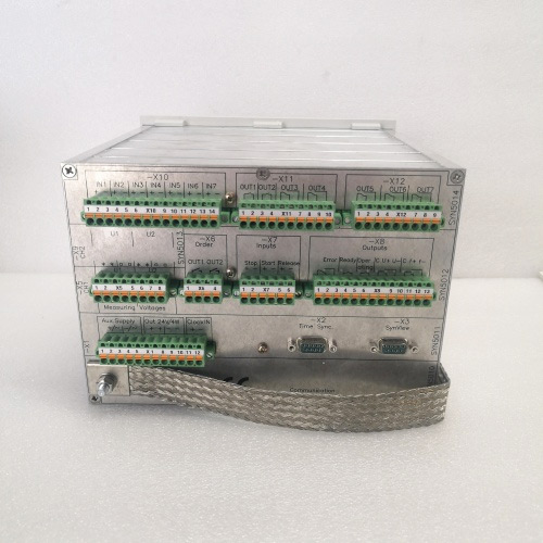
ABB TINT-4331
ACS580 Inverter Board Installation & Configuration Guide
Phase 1 — Pre-Installation (est. 10 min)
De-energize the cabinet and enforce a 5-min discharge wait for safety. Gather your tools list (multimeter, insulated screwdrivers, Torx set). Perform critical backup tasks: complete a program export and snap high-resolution photos of all DIP switches, wiring runs, and the overall rack layout.
Phase 2 — Removal (est. 5 min)
Always label wires before disconnecting. Carefully release the DIN rail latch holding the chassis. Pull the module perpendicular to the backplane to avoid bending pins. Inspect the backplane connector pins for any signs of thermal stress.
Phase 3 — Installation (est. 10 min)
Put on your ESD first. Verify the part number matches. Replicate your exact DIP/jumper config from the photos. Seat the ABB TINT-4331 until the latch clicks securely. Reconnect all wiring (~0.5 N·m of torque). Run your standard pre-power checklist.
Phase 4 — Power-On & Testing (est. 15 min)
Verify the supply voltage measures 24 V DC ±10%. Observe the LEDs (green = RUN / red flash = ERR / amber flash = DIAG). Connect your programming software and execute a program download. Run a complete functional test covering I/O points, comms, and one full control loop. Confirm >30 min stable operation. Finally, log the swap in your maintenance record.
Troubleshooting quick-reference:
- No comms → check IP, cable, switch port
- ERR steady → firmware mismatch; attempt update
- Download fails → check cable and software version
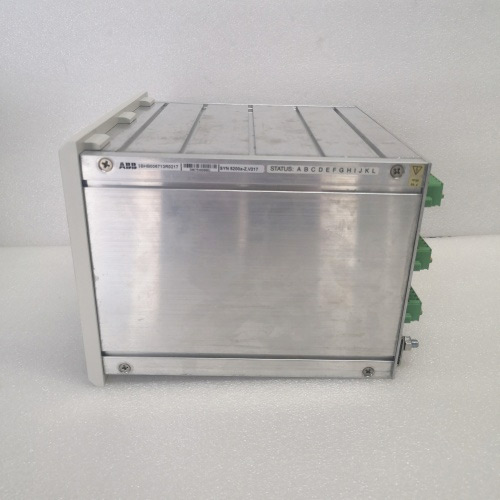
ABB TINT-4331
Quality Transparency (SOP) for PCB Inspection
- Incoming Inspection: We trace source documents (OEM packing list / customs docs) and run an anti-counterfeit check (serial number + security label). Visual physical inspection confirms no corrosion, scratches, repair marks, or yellowing. We verify all included accessories.
- Live Functional Test: We initiate a power-on self-check monitoring LEDs and startup behavior. The communication handshake is tested via Modbus/Profibus/EtherNet-IP. We run a full I/O signal simulation followed by a load test >24 hrs with temperature rise logged. We output a formal Test Report.
- Electrical Tests: Technicians check insulation resistance using a 500 V megohmmeter (>10 MΩ). We also verify ground continuity and run a dielectric withstand sequence. We use a Fluke 115 multimeter.
- Firmware Verification: The exact version is read and recorded. All original DIP switch/jumper settings are photographed.
- Final QC & Packaging: Following technician sign-off, the PCB goes into an anti-static bag (sealed). We secure it with bubble wrap + box and apply a QC Passed label with the date. Test photos/video available on request. The unit is confirmed functional after all tests above.
Technical Pitfall Guide for VFD Repairs
- Firmware mismatch — Always record the original control unit firmware version before removal. Specify the required version range when ordering your replacement ABB TINT-4331 to ensure direct handshake compatibility. I spent three hours troubleshooting a drive fault only to find the new board required v3.0+ firmware.
- DIP switch / jumper misconfiguration — Photograph everything before removal. Replicate the layout exactly on the new unit. Remember: the 120 Ω termination resistor is required at the comms bus ends only. “Photo. Photo. Photo.”
- Terminal / cable incompatibility — Verify the internal wiring diagram before ordering. Confirm the shield grounding method on the motor cables. ❗ Do not guess the pinouts. Swapping the U and V phase gate leads will instantly destroy the main switching module.
- PSU capacity — If you are building a custom drive cabinet, calculate total internal rack power + 20% headroom. Add a second 24 V DC PSU if you run near the limit with auxiliary cooling fans. Starving the logic hardware causes random nuisance trips.
- ESD — Use a wrist strap + ESD mat. Exercise extra caution in dry winter conditions. “I watched an engineer skip the strap in January. The module smoked on power-up. $2,000 gone.”
Keep these five points in mind and you’ll cut 90% of your rework time.
Frequently Asked Questions about the 3AXD50000 Series
1. Can I just drop this in and go?
Yes, assuming your drive frame matches. The ABB TINT-4331 handles hardware-level power and gating. It does not store the main application program, which lives on the separate control unit, so no reprogramming is needed.
2. Are the gate drive output headers on this board pin-compatible with older ACS550 models?
No. The architecture differs completely between generations.
| Feature | ACS580 (Current) | ACS550 (Legacy) |
| Control Link | Digital ribbon bus | Analog multi-pin |
| Gate Driver | Integrated PCB | Separate sub-assemblies |
3. I am running an ACS580-046A-4 chassis — will this fix an IGBT short?
Honestly, we’ve seen this exact scenario play out multiple times. Replacing the driver board restores the gate signal, but if the physical power module has a dead short across the silicon, you must replace the power block first. Installing a new PCB onto a shorted module will instantly destroy the replacement. Well, technically it might power up for a millisecond, but you risk violent failure.
4. How do I verify the control voltage after installation?
- Power up the drive chassis.
- Set your multimeter to V DC.
- Probe the internal auxiliary power terminals on the control block.
- Verify the reading falls between 21.6 V and 26.4 V.
Once you install the ABB TINT-4331 and power up, the main controller authenticates it within 10 seconds.
5. What happens if I forget the ESD strap during replacement?
The damage depends on the static charge.
- Low discharge: Degrades logic gates. The system boots initially but fails weeks later with random communication drops.
- High discharge: Instantly arcs across the processor pins. The board refuses to boot, and the panel displays a steady red ERR LED.
To be frank, skipping ESD protocols is the fastest way to void your warranty.



 Start Chat


