

Description
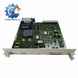
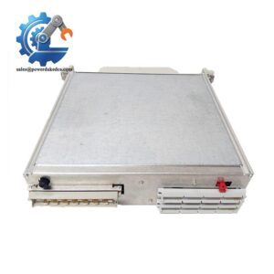
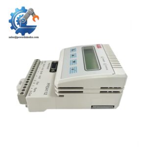
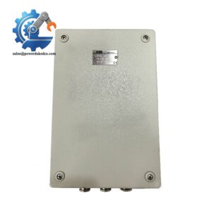
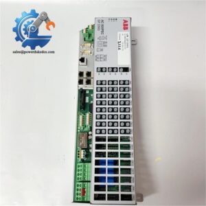
ABB 3BHB002751R0106 XVC722AE01 Industrial I/O Control Module
SEO Titles
1. ABB XVC722AE01 3BHB002751R0106 | Integrated Analog & Digital I/O Module for DCS System
2. ABB 3BHB002751R0106 XVC722AE01 | 12-bit Resolution Industrial Control I/O Module
3. ABB XVC722AE01 | In Stock Original Industrial Automation Spare Part with 12-month Warranty
4. ABB 3BHB002751R0106 | Direct Replacement DCS I/O Module for Process Automation Systems
5. ABB XVC722AE01 3BHB002751R0106 | Galvanically Isolated Extreme Condition I/O Module
Product Core Brief
- Model: 3BHB002751R0106 / XVC722AE01
- Brand: ABB
- Series: XVC Industrial Control Module Series
- Core Function: Executes mixed analog and digital signal acquisition and output for process control systems
- Product Type: Integrated I/O Control Module
- Key Specs: 12-bit signal resolution, full-module galvanic isolation, extreme temperature adaptability
- Condition: New Original, non-refurbished surplus stock
⚠️ Discontinued original production, limited inventory available
Product Introduction
Field automation failures often stem from incompatible I/O signal processing and weak anti-interference hardware—this is exactly where the ABB (3BHB002751R0106) delivers stable performance. It is a dedicated integrated I/O module designed for ABB distributed control systems, widely deployed in petrochemical, power generation and metallurgy process automation sites.
Unlike ordinary universal I/O modules, this unit supports flexible analog input configuration and built-in fast counter functions. It adopts 12-bit signed high-precision signal conversion and independent galvanic isolation design for the entire module. Verified by ABB official datasheets, it maintains stable signal output and acquisition accuracy under high electromagnetic interference environments. Its XC extreme-condition design allows reliable operation in fluctuating industrial ambient temperatures, effectively reducing field signal drift and system misjudgment failures.
Key Technical Specifications
| Parameter Item | Technical Data |
|---|---|
| Full Model Number | 3BHB002751R0106 () |
| Module Type | Mixed Analog & Digital I/O Control Module |
| Analog Input Configuration | 4-channel 2-wire/single-ended or 2-channel 3-wire/differential selectable |
| Analog Output Quantity | 2 channels (voltage/current compatible) |
| Signal Resolution | 12-bit including sign bit |
| Digital Input | 8-channel 24 V DC group input |
| Digital Output | 8-channel 24 V DC, max 0.5 A per channel |
| Special Function | Integrated fast counter module |
| Isolation Design | Full-module galvanic isolation |
| Environmental Grade | XC grade for extreme industrial ambient conditions |
| Applicable System | ABB DCS Process Automation System |
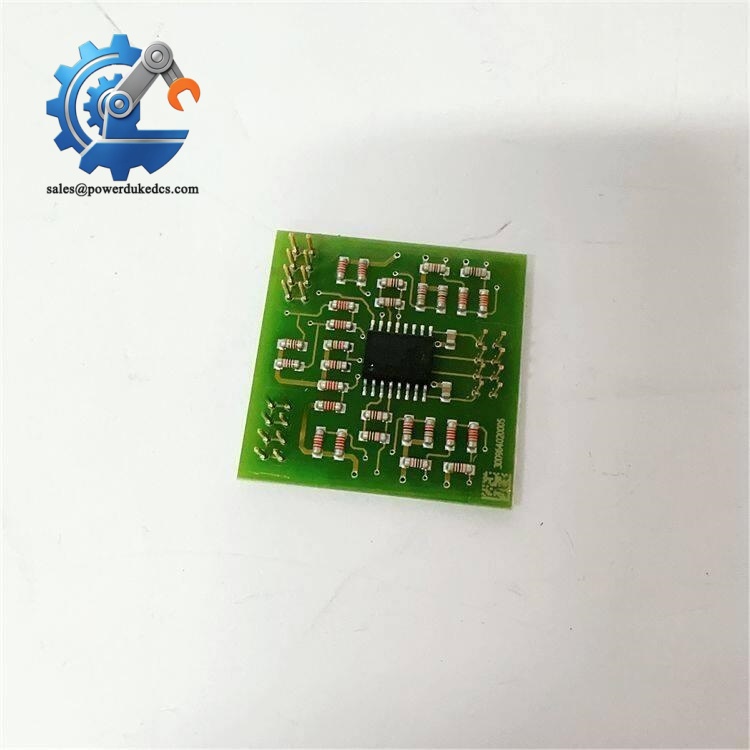
ABB 3BHB002751R0106 XVC722AE01
Installation & Configuration Guide
Stage 1: Pre-Installation Preparation (10 mins)
⚠️ Safety Preconditions
Notify production teams of scheduled downtime. Switch all on-site process valves and driven equipment to safe stop status. Cut off all control cabinet power including UPS backup power. Wait 5 minutes for internal capacitor full discharge to avoid electric shock or module burnout.
Tool Preparation
ESD wrist strap and anti-static mat, PH1 cross screwdriver, Fluke 115 multimeter, label marker, mobile phone for configuration recording.
Data Backup
Export the complete running program of the control system to USB disk and cloud storage. Take clear photos of the old module’s terminal wiring status and DIP switch positions for 1:1 configuration replication.
Stage 2: Old Module Removal (10 mins)
Step 1: Remove the module front protective cover by pressing the side buckles gently.
Step 2: Loosen terminal screws counterclockwise, label each cable corresponding to terminal numbers, and detach wires slowly without pulling hard.
Step 3: Press down the bottom DIN rail buckle with a flat screwdriver, pull the module outward vertically to separate from the backplane connector.
Step 4: Inspect backplane pins for bending or oxidation. Blow clean dust with compressed air if needed; do not touch pins directly.
⚠️ Key Reminder: Save all configuration labels on the old module before removal, these on-site parameters cannot be fully matched by factory default settings.
Stage 3: New Module Installation (15 mins)
Step 1: Wear ESD protective gear before taking the new module out of anti-static packaging.
Step 2: Verify the full model 3BHB002751R0106 / matches the replacement requirement to avoid model mismatch.
Step 3: Replicate DIP switch and terminal resistor settings strictly according to old module photos, especially bus terminal resistance ON/OFF status.
Step 4: Align the module with the backplane anti-error slot, press vertically until a click sound confirms locking in place, check horizontal alignment with adjacent modules.
Step 5: Restore wiring one by one per labeled records, fasten screws with moderate torque (about 0.5 N·m), and tug wires slightly to confirm firm connection.
Self-Check List
DIP switch settings correct ✅ | All cables connected ✅ | Module fully locked ✅ | No residual tools in cabinet ✅
Stage 4: Power-On & Functional Testing (20 mins)
Pre-power check: Measure 24V DC power voltage to confirm ±10% tolerance. Test insulation resistance between power and ground to ensure value over 10kΩ with no short circuit risk.
Step 1: Power on the control rack independently first, observe module LED status: steady green RUN light means normal startup; flashing red ERR light indicates configuration or firmware exceptions.
Step 2: Connect ABB official configuration software, scan network nodes to identify the new module, read and record firmware version information.
Step 3: Import the pre-backed-up program, compile and download completely, switch the system to RUN mode.
Step 4: Conduct full-range analog signal simulation and digital I/O trigger tests to verify accurate signal response.
Step 5: Keep the system running continuously for 30 minutes, confirm no alarm codes and stable data transmission, then file replacement records including module serial number and replacement date.
Troubleshooting Tip: Communication timeout faults are mostly caused by unmatched firmware versions. Reflash or downgrade firmware to match the on-site system version to fix the issue.
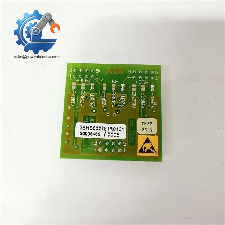
ABB 3BHB002751R0106 XVC722AE01
Quality Inspection Process
We implement full-process quality control for all ABB industrial spare parts to eliminate hidden risks of inventory parts.
1. Warehouse Entry Verification
Verify original factory packing list and customs declaration documents for source traceability. Check official serial number query results and anti-counterfeit labels. Inspect module surface for no corrosion, scratch, yellowing or disassembly traces. Complete accessory inspection including factory certificate and specification documents.
2. Live Functional Test
All modules are tested on a standard ABB DCS test rack. Complete power-on self-test, bus communication handshake and full-scale I/O signal simulation tests. Conduct 24-hour continuous aging operation to monitor temperature rise and operating stability. Formal test reports are generated for each unit.
3. Electrical Performance Detection
Adopt 500V megohmmeter for insulation resistance testing, with qualified data over 10MΩ. Complete ground continuity and pressure resistance tests as standard procedures to ensure electrical safety compliance.
4. Firmware & Configuration Confirmation
Read and record factory firmware version, back up default configuration parameters and DIP switch settings. Provide version matching suggestions according to mainstream on-site system versions.
5. Final QC & Packaging
Certified inspectors confirm all test items pass. Seal modules with anti-static bags, pack with bubble film and cartons, and attach QC Pass labels with test dates. Test videos and photos can be provided upon customer request.
Field Replacement Pitfall Guide
Based on on-site maintenance experience, most module replacement failures come from trivial operational errors rather than product quality problems.
❗ Firmware Version Mismatch
New modules with updated firmware often fail to communicate with old on-site DCS systems. We once encountered a site where engineers replaced the module directly without version checking, resulting in 2-day communication timeout faults. Always record the original firmware version before replacement and confirm version compatibility with suppliers in advance.
❗ DIP Switch Configuration Errors
This is the most frequent on-site mistake. Default factory switch settings do not match field bus address and baud rate parameters. Take photos before disassembly—replicate every switch position 1:1 to avoid bus node conflict and signal failure.
❗ Terminal Wiring Definition Differences
Even for identical model numbers, batch iteration may cause minor pin definition changes. Do not rely on experience; check the official wiring diagram before wiring to prevent wrong connection burning of I/O channels.
❗ On-Site Power Load Calculation Neglect
Adding new I/O modules increases rack power consumption. Failure to reserve 20% power margin may cause unstable power supply and intermittent system alarms. Calculate total load before replacement and upgrade power modules if necessary.
❗ ESD Static Damage
Dry industrial environments carry high static electricity. We have seen unprotected operation directly burn out module internal circuits, causing irreparable damage. Always use anti-static tools during disassembly and installation.
Master these key points, and you can avoid over 90% of on-site replacement rework and unplanned downtime.
Frequently Asked Questions (FAQ)
1. Is the ABB module fully compatible with old-generation ABB DCS systems?
It depends on your system firmware version. This module supports most mainstream ABB process automation systems. For system versions below V5.0, firmware downgrade is required to ensure stable communication. We can complete version matching and debugging before delivery.
2. Can this module support hot-swap replacement during system operation?
It does not support live hot swapping. You must cut off rack power for replacement. Hot plugging will cause instantaneous current impact, easily damaging the backplane connector and module internal chip, and triggering system bus faults.
3. What is the warranty policy for this 3BHB002751R0106 module?
All our stock units enjoy a 12-month formal warranty. We provide complete test reports before delivery. Non-human damage faults within the warranty period support free replacement and technical after-sales guidance.
4. What is the difference between and ordinary universal I/O modules?
This XC-grade module adopts enhanced encapsulation and anti-interference design, suitable for high-temperature, high-vibration extreme industrial environments. It supports flexible analog channel configuration and integrated fast counter function, with higher signal acquisition accuracy than ordinary modules.
5. How long is the delivery cycle for this discontinued module?
We have physical stock in warehouse. Orders can be shipped within 1-3 working days. As original production is discontinued, inventory is limited, and stock status is subject to real-time confirmation.
6. Will the module have signal drift after long-term operation?
With 12-bit high-precision conversion and full galvanic isolation design, the module maintains stable signal output. On-site verified data shows negligible drift under standard operating conditions. Regular system calibration can further guarantee long-term operational accuracy.



 Start Chat


