

Description
Product Core Brief
- Model: DASO110 57120001-AT1
- Brand: ABB
- Series: S100 I/O, Advant Master / Advant OCS DCS System
- Core Function: Convert digital controller signals into standard analog outputs to regulate field actuators
- Type: Analog Output Module
- Key Specs: 4 galvanically isolated channels, 0–10 V / 0–20 mA, ±0.05% full scale accuracy
- Condition: New Surplus, non-refurbished ⚠️ Original production discontinued, limited stock on hand
Product Introduction
Unstable analog control signals directly affect precision regulation of valves and drives in continuous process plants. The ABB DASO110 57120001-AT1 acts as a standard output interface inside legacy Advant DCS racks. It receives digital data via rack backplane and generates continuous analog signals to drive on-site process equipment.
This module carries four fully separated output channels to suppress electromagnetic interference from motors and switchgear. It features 12-bit conversion resolution and maintains tight accuracy within normal cabinet operating temperatures. Units of this type have run reliably for decades in power, pulp and chemical sites. One practical detail to keep in mind: mismatched terminal bases will stop channels from working properly after replacement.
Key Technical Specifications
| Parameter Item | Technical Value |
|---|---|
| Type Designation | DASO110 |
| Material No. | 57120001-AT1 |
| Channel Count | 4 independent analog output channels |
| Signal Options | 0–10 V DC, 0–20 mA DC |
| Basic Accuracy | ±0.05% FS at 25 °C |
| Resolution | 12-bit |
| Isolation | Channel to backplane galvanic isolation |
| Supply Voltage | 24 V DC ±10% |
| Operating Temperature | -20 °C to +60 °C |
| Humidity Range | 5% – 95 %, non-condensing |
| Protection Class | IP20 (for rack installation) |
| Matching Terminal Unit | DSTA160 |
| Platform Compatibility | Advant Master, Advant OCS S100 I/O rack |
Installation & Configuration Guide
Stage 1: Pre-Installation Preparation (10 Minutes)
⚠️ Safety Priority Inform operation staff of planned downtime. Shift all controlled equipment to safe manual status. Cut power to the complete I/O rack including UPS feed. Allow minimum 5 minutes for internal capacitors to discharge.
Tool Preparation ESD wrist strap and anti-static mat, PH1 screwdriver, Fluke 115 multimeter, marker pen, label tape, mobile camera for recording wiring and jumper positions.
Backup & Recording Export the complete controller project. Take clear photos of field wiring, jumper settings and module position. These records prevent configuration errors during commissioning.
Stage 2: Old Module Removal (12 Minutes)
- Photograph terminal wiring before disconnecting any field cables, mark each wire by channel number.
- Loosen terminal screws counterclockwise and pull wires out gently. Do not yank cables to avoid damaged terminals.
- Release the front locking latch, pull the module straight outward away from the backplane. Avoid twisting the circuit board.
- Inspect backplane pins for bending, corrosion or dust. Clean debris with dry compressed air if necessary.
⚠️ Note: Copy down any handwritten configuration marks on the old module before storage.
Stage 3: New Module Installation (15 Minutes)
- Wear ESD protection before removing DASO110 57120001-AT1 from anti-static packaging.
- Double-check full part number matches the removed hardware.
- Recreate jumper settings exactly according to photos from the original module; each channel can be set for voltage or current output.
- Slide the module along rack guides, push fully home until the front latch clicks and locks.
- Reconnect field cables following labeled records. Tighten terminals with moderate torque, lightly pull each wire to confirm stable contact.
Self-Check List Channel jumpers confirmed ✅ | All field cables reconnected ✅ | Module securely locked ✅ | No loose tools left in cabinet ✅
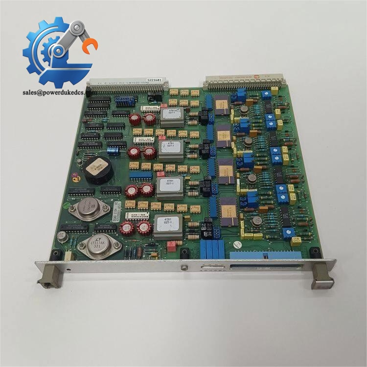
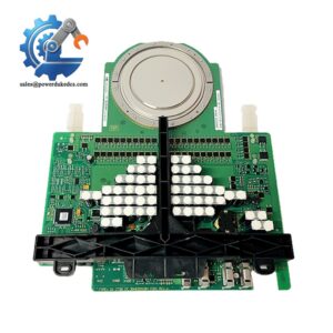
ABB DASO110 57120001-AT1
Stage 4: Power-On & Functional Testing (20 Minutes)
Carry out short-circuit resistance check across power terminals before rack energization.
- Restore power to the I/O rack only, observe module status LED. Constant power indicator means basic initialization succeeds.
- Launch engineering software, scan the I/O rack and verify the controller detects DASO110.
- Load saved configuration and confirm signal mode aligns with connected field devices.
- Force output values channel by channel, measure analog signals at field terminals with multimeter and check linearity.
- Keep the system running continuously for 30 minutes. Monitor for unexpected fluctuation or fault alarms. Record module serial number and replacement date in maintenance logs.
⚠️ Common fault hint: Zero output on all channels is usually caused by incorrect voltage/current jumper selection.
Frequently Asked Questions (FAQ)
1. Can DASO110 57120001-AT1 be hot swapped on a powered S100 rack? No. This legacy S100 I/O module does not support hot insertion. The I/O rack must be fully powered down before removal or fitting. Hot swapping may destroy backplane connectors and trigger system-wide DCS alarms.
2. Does this module work on every Advant OCS I/O rack directly? It cannot work without the matching DSTA160 terminal base. Mounting the module on an incompatible connection unit changes wiring definitions, and signals cannot reach field actuators.
3. What separates DASO110 from its successor DASO120A? DASO120A is the official upgraded replacement. The physical footprint and terminal layout differ entirely, requiring complete rewiring of field cables. Select original DASO110 if you want to avoid cabinet rewiring work.
4. Is voltage or current mode configurable per individual channel? Yes. On-board hardware jumpers define signal type for each channel. Adjust jumpers only when power is fully disconnected. Never modify jumpers while energized.
5. What warranty coverage do you offer for DASO110 units? We provide 12-month warranty. Every module undergoes complete functional bench testing before dispatch. Test photos or video can be provided on request. Damage from improper wiring or ESD neglect is not covered.
6. What maximum load resistance is allowed on current output channels? For 0–20 mA output mode, maximum permitted load resistance is 600 Ω. Higher resistance limits signal range and leads to unstable valve positioning.
I can attach the complete incoming inspection & live test QC procedure below FAQ if you need it for your product webpage.



 Start Chat


