

Description
- ABB REF541KM118AAAA | Integrated Measurement, Control & Fault Locator For Distribution Networks
Product Core Brief
- Model: REF541KM118AAAA
- Brand: ABB
- Series: REF 54 ProtectIT Feeder Terminal Series
- Core Function: Deliver integrated protection, measurement, control and supervision for medium voltage feeders
- Type: Medium Voltage Feeder Protection IED (Intelligent Electronic Device)
- Key Specs: 15 binary inputs / 12 relay outputs; built-in fault locator; programmable logic function
- Condition: New Surplus, factory tested
- Lifecycle Notice: ⚠️ Original production discontinued since 2022, limited remaining stock
Product Introduction
Key Technical Specifications
- Full Order Code: REF541KM118AAAA
- Application Object: MV feeders, asynchronous motors, capacitor banks
- Main Protection Functions: Directional / non-directional overcurrent protection, earth fault protection, thermal overload, residual voltage supervision, auto-reclosing
- I/O Configuration: 15 binary inputs, 12 galvanic isolated output relays
- Measurement Functions: Phase current, line voltage, power factor, active/reactive energy, THD power quality monitoring
- Communication Interfaces: SPA bus, LON bus, IEC 60870-5-103, Modbus RTU; IEC 61850 available via external SPA-ZC 400 adapter
- Configuration Tool: CAP 505 relay configuration software
- Auxiliary Supply: 24 V DC / 48 V DC / 110 V AC/DC / 220 V AC/DC (variant dependent)
- Mounting: Standard 19-inch rack / flush mounting in switchgear
- Operating Temperature: -20 °C ~ +55 °C
- Humidity Range: 5 % – 95 % RH, non-condensing
- Standards Compliance: CE certified, meets relevant IEC protection relay standards
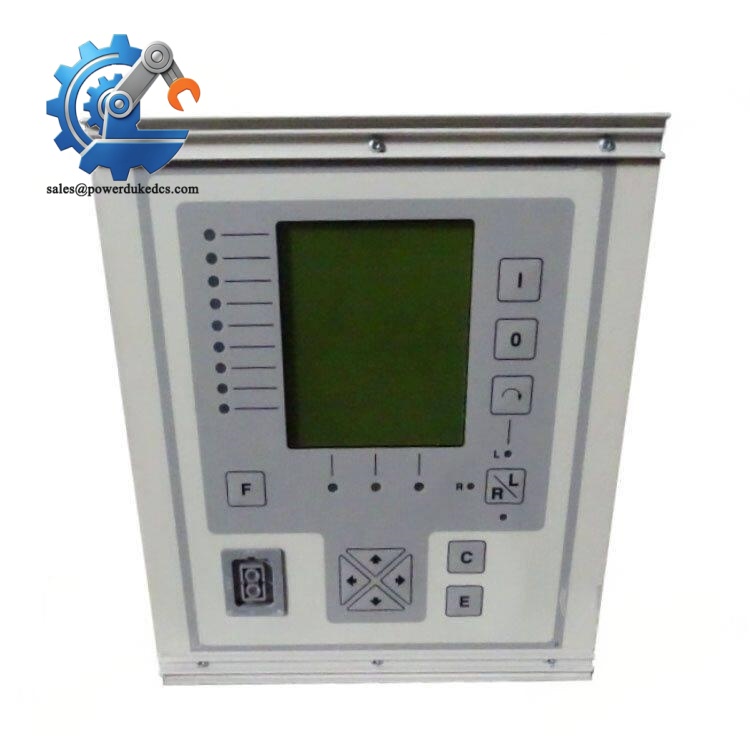
ABB REF541KM118AAAA
Installation & Configuration Guide
Pre-Installation Preparation (20 mins)
Complete lockout-tagout procedures for medium voltage primary circuit and secondary control circuits. Confirm all CT circuits are short-circuited before wiring work. Allow 5 minutes for equipment residual charge discharge.
ESD wrist strap, insulated screwdrivers, Fluke multimeter, torque screwdriver, mobile phone for wiring recording, laptop with CAP 505 software.
Export the full parameter set from the existing relay and save offline. Capture photos of all CT/PT secondary wiring and binary I/O terminal connections. Confirm auxiliary supply voltage matches the device rating.
Old Relay Removal (15 mins)
Step 2: Label each secondary wire sequentially and disconnect terminals one by one.
Step 3: Remove mounting screws and pull the feeder terminal steadily outward.
Step 4: Inspect rear wiring terminals and rack mounting frame for corrosion or loose hardware.
New REF541KM118AAAA Installation (20 mins)
Step 2: Verify full model code REF541KM118AAAA. Different suffix versions carry fixed I/O and function configurations and cannot be swapped blindly.
Step 3: Fix the relay on the switchgear panel, keep proper ventilation gaps around housing.
Step 4: Reconnect CT, PT, binary input, output relay and auxiliary power cables strictly based on recorded photos. Remove CT shorting links after all wiring finishes.
All CT shorting links removed ✅
Auxiliary supply wiring polarity correct ✅
Terminal screws tightened to recommended torque ✅
No foreign debris left inside cabinet ✅
Power-On & Commissioning (40 mins)
Step 1: Switch on auxiliary control supply and wait for relay self-test cycle. Confirm no permanent fault alarms on front HMI.
Step 2: Connect laptop via front optical port, upload saved parameter database from CAP 505 software.
Step 3: Verify protection setting values, logic scheme, auto-reclosing sequence and fault recording trigger conditions.
Step 4: Conduct secondary injection test to validate tripping curves and output relay action.
Step 5: Establish communication connection with upper SCADA system, check real-time measured data and alarm signal transmission.
Step 6: Maintain continuous operation monitoring for minimum 30 minutes, store disturbance record template and final parameter file.
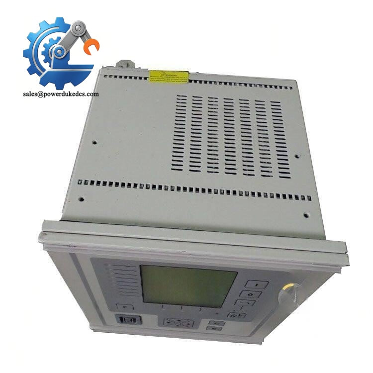
ABB REF541KM118AAAA
Quality Inspection Process
- Incoming Visual Inspection
Check housing integrity, front keypad and display status. Confirm complete model marking, no scratch, disassembly or burn traces.
- Power-On Self-Test
Apply rated auxiliary supply, run full startup self-diagnosis, verify LCD display and LED indicator performance.
- I/O Continuity Test
Carry out binary input excitation and output relay actuation test to confirm all channels respond normally.
- Communication Verification
Test SPA or IEC 60870-5-103 communication handshake with simulation host.
- Parameter Storage Check
Download and upload configuration files to confirm stable memory storage.
- Data Archiving & Packaging
Record serial number and test logs for traceability. Seal inside anti-static bag with bubble wrap, attach QC Pass shipping label.
Field Replacement Pitfall Guide
REF541 contains dozens of suffix variants. KM118AAAA defines fixed I/O allocation and function package. Using mismatched variants leads to unavailable protection functions.
Never disconnect CT wires without installing shorting links. Open CT secondary generates lethal high voltage and endangers personnel safety.
If no parameter backup exists before replacement, all protection curves, interlock logic and communication settings need re-engineering, which extends site downtime significantly.
Long-term operation above +55 °C ambient temperature accelerates internal component ageing and triggers random self-supervision faults.
Rough plugging and pulling of optical programming cable can damage the internal optical transceiver module.
When IEC 61850 communication is required, confirm SPA-ZC 400 adapter firmware version matches REF541 software release.
Frequently Asked Questions (FAQ)
-
What applications fit REF541KM118AAAA?
It is designed for medium voltage feeder protection, also applicable for MV asynchronous motors and shunt capacitor bank control inside industrial distribution substations.
-
Can I directly copy parameters from an old REF541 unit?
Yes, provided both units share identical suffix codes. Parameter migration is supported via CAP 505 configuration software.
-
Does this relay support disturbance fault recording?
Built-in fault recorder captures voltage and current waveforms during short-circuit or earth fault events, supporting post-fault analysis and fault location calculation.
-
Is hot swapping supported?
Hot swap is prohibited. Auxiliary power and all secondary circuits must be de-energised before removal or installation.
-
Can I upgrade firmware on site?
Firmware update is available via CAP 505 software. Users should confirm firmware compatibility, as major version changes may reset configured parameters.
-
What warranty applies to stocked units?
All REF541KM118AAAA units carry a 12-month warranty. Damage caused by wrong wiring, overvoltage surge and static discharge is excluded.
-
What is the recommended replacement model for REF541 series?
ABB’s REF615 or REF635 serves as modern successor. Direct plug-and-play replacement usually requires modification to wiring and protection settings.



 Start Chat


