

Description
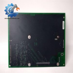
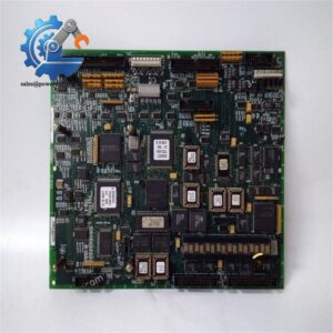
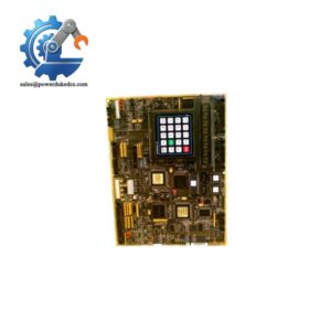
- GE DS200FSAAG2ABA | OEM Field Supply Gate Amplifier Board for Power Generation
Product Core Brief
- Model: DS200FSAAG2ABA
- Brand: General Electric (GE)
- Series: Speedtronic Mark V Turbine Control System
- Core Function: Amplifies control signals to regulate generator field excitation current
- Type: Field Supply Amplifier Board (FSAA)
- Key Specs: Configurable via JP1-JP6 jumpers | Built-in 30A fast fuses | Rack mount form factor
- Condition Note: GE discontinued original production; available as fully tested surplus units, not factory new production
Key Technical Specifications
| Parameter | Specification |
|---|---|
| Full Part Number | DS200FSAAG2ABA |
| Board Name | Field Supply Amplifier Board (FSAA) |
| Compatible System | GE Speedtronic Mark V Gas & Steam Turbine Control |
| Onboard Configuration | JP1–JP6 Berg-style jumpers for operational mode selection |
| Overcurrent Protection | Dual 30 A, 60 V fast-acting fuses |
| External Connectors | 1 × 10-pin connector, 4 × 2-pin terminal connectors |
| Operating Temperature Range | -20 °C ~ +60 °C |
| Mounting Standard | Mark V standard rack chassis installation |
| PCB Coating | Standard conformal coating |
| Origin | United States |
| Signal Function | Converts control commands into regulated field excitation drive signals |
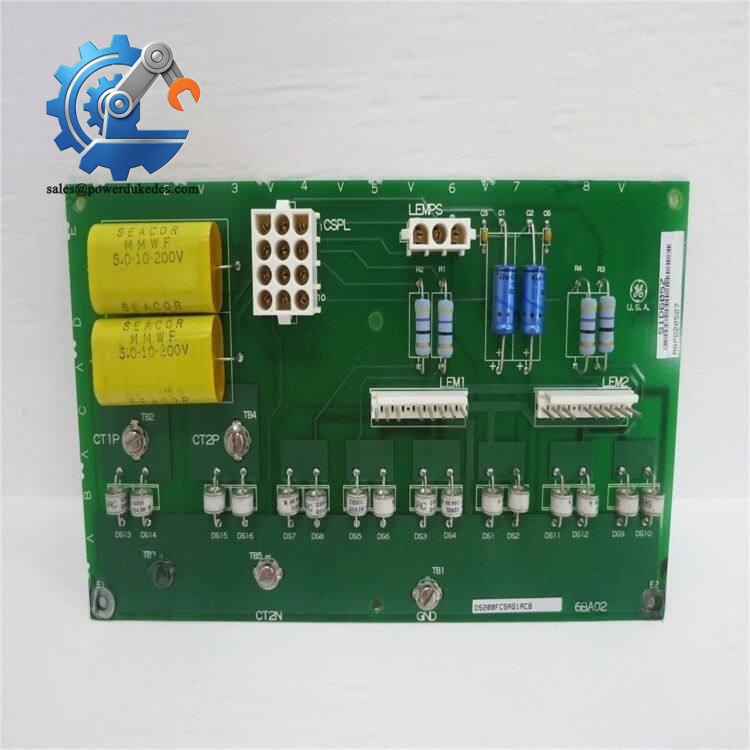
GE DS200FSAAG2ABA
Product Introduction
GE DS200FSAAG2ABA is a dedicated field supply amplifier board engineered exclusively for the GE Speedtronic Mark V turbine control platform. It receives low-level control signals from the main processor and outputs amplified drive signals to govern generator field winding excitation.
This board maintains stable generator output voltage under fluctuating load conditions. It includes hardware fuse protection and configurable jumpers to match site excitation parameters. As an obsolete critical spare for power generation facilities, bench testing is mandatory before deployment to eliminate hidden component aging risks for continuous running turbine assets.
Application Scenarios & Pain Points
Unplanned turbine trips triggered by unstable generator voltage often trace back to degraded excitation control hardware. A faulty FSAA board distorts field current regulation, which can trigger generator protection trips and force unit shutdown. For base-load power plants, every unplanned outage creates substantial financial losses.
Typical Application Scenarios:
- Combined-cycle power plants – GE Frame gas turbine Mark V control cabinets, generator excitation regulation
- Thermal power stations – Steam turbine generator field control and voltage stabilization
- Offshore oil & gas facilities – Turbogenerator sets operating under unstable grid load
- Industrial co-generation plants – Legacy Mark V system maintenance and spare backup
Case ReferenceA coastal combined-cycle power plant experienced repeated generator voltage oscillations in 2025. Technicians traced the fault to aging electrolytic capacitors on the original DS200FSAAG2ABA. The facility held no spare inventory, and OEM lead time exceeded 10 weeks. After installing our fully bench-tested DS200FSAAG2ABA spare unit, excitation regulation returned to stable parameters. The plant later added two identical boards to their critical spare inventory to avoid extended downtime.
Compatibility & Replacement Matrix
→ DS200FSAAG2A : Direct replacement; verify all JP1-JP6 jumper positions before power-up → Mark VIe excitation control boards : Not compatible; different hardware architecture and signal logic → Generic aftermarket clones : Full bench validation required; jumper definitions and drive thresholds may mismatch OEM standards
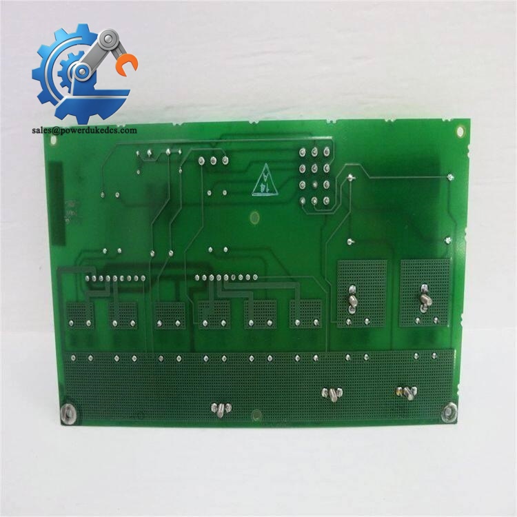
GE DS200FSAAG2ABA
Quality Control Procedure (SOP)
- Incoming InspectionSerial number and PCB trace verification; visual inspection for corrosion, burnt components, cracked solder joints and capacitor bulging. All labeling and fuse holders are cross-checked.
- Bench Functional Live TestTest platform built on GE Mark V simulation rack. Complete power cycle test, LED status verification, low-level control signal input simulation, excitation drive output validation, and fuse continuity check. A formal test report will be generated.
- Electrical Parameter TestingInsulation resistance test at 500 VDC; supply circuit stability measurement; connector continuity inspection.
- Circuit & Configuration RecordingDocument all jumper positions (JP1–JP6). Photograph original settings for customer reference. Capacitor aging assessment is performed for surplus units.
- Final QC & PackingQC engineer signs test report. The board is sealed in anti-static bag, packed with bubble wrap, and labeled with QC pass date. Test photos and reports can be provided upon request.
Field Installation Pitfall Guide
- Jumper Configuration MismatchFault risk: Incorrect jumper settings cause improper excitation current regulation, leading to voltage drift or generator trips.Tip: Take clear photos of jumpers on the original board before removal. Reproduce every jumper position on the replacement unit before power-on. Many site faults come from this avoidable error.
- ESD DamageRisk: Unprotected bare-hand contact destroys onboard semiconductors.Tip: Wear ESD wrist strap and operate on anti-static mat. Dry winter environments carry higher electrostatic risk. I have witnessed a unit damaged within seconds after direct unprotected contact.
- Improper Fuse ReplacementRisk: Installing non-rated slow-blow fuses removes overcurrent protection and risks permanent PCB burnout.Tip: Only fit 30 A fast-acting 60 V fuses matching OEM specifications. Do not upsize fuse ratings.
- Loose Terminal ConnectionsRisk: High resistance at terminals creates thermal hotspots during heavy excitation loading.Tip: Torque all wiring terminals to site specified values; inspect crimp quality before cabinet closure.
- Capacitor Aging for Surplus BoardsRisk: Long-stored surplus units may have degraded capacitors without visible signs.Tip: Request full load thermal test records when purchasing surplus stock.



 Start Chat


