

Description
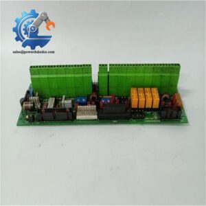
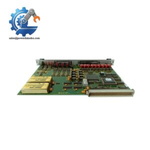
- GE DS200ADGIH1AAA | Genuine DS200 Series Auxiliary Interface Board
Product Core Brief
- Model: DS200ADGIH1AAA
- Brand: General Electric (GE)
- Series: Mark V Speedtronic Turbine Control System (DS200 series)
- Core Function: Auxiliary signal interface for gas & steam turbine control racks
- Type: Auxiliary Interface Board
- Key Specs: 40-pin + 6-pin connectors | 60 configurable jumpers | Built-in circuit test points
⚠️ Discontinued by OEM, limited stock available
Condition: New Surplus, not refurbished
Key Technical Specifications
| Parameter | Specification |
|---|---|
| Full Part Number | DS200ADGIH1AAA |
| Applicable System | GE Mark V Speedtronic Turbine Control |
| Form Factor | 8 in × 6 in PCB board mounting design |
| Hardware Connectors | 1 × 40-pin connector, 1 × 6-pin connector |
| Configuration | 60 configurable jumpers, multiple onboard test points |
| Mounting | 4-point screw fixation for control cabinet rack |
| Operating Temperature | -40 ℃ ~ +70 ℃ |
| Protection Class | IP20 (cabinet installation only) |
| Primary Application | Signal routing and auxiliary communication inside turbine control rack |
| OEM Status | Officially discontinued component |
| Compatibility | Standard Mark V DS200 rack hardware |
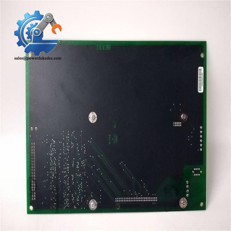
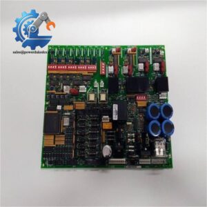
GE DS200ADGIH1AAA
Product Introduction
Application Scenarios & Pain Points
- Thermal Power Industry – Steam Turbine Control
Used for auxiliary signal transmission of boiler steam turbines. Stable signal communication is required to guarantee turbine protection interlock logic.
- Oil & Gas Industry – Gas Turbine Drives
Applied to gas turbine sets at refineries and compressor stations. Continuous production cannot afford long downtime waiting for OEM spare parts.
- Cogeneration Plants – Combined Cycle Units
Legacy Mark V control racks are widely equipped in medium-sized cogeneration projects. Operators need reliable spare inventory to support annual overhaul and emergency repair.
- Industrial Waste Heat Power Generation
Older waste heat power generation units adopt Mark V systems; interface board faults often trigger turbine trip alarms.
Last winter, a regional thermal power plant encountered a DS200ADGIH1AAA hardware fault on its 120MW steam turbine Mark V control rack. The control system continuously reported abnormal auxiliary signal alarms.
Compatibility & Replacement Matrix
Notes: Must copy original jumper positions before power-up; inconsistent jumper settings will lead to signal mismatch and system alarms.
No official cross-model alternative boards. Any other DS200 series PCB cannot be used for direct substitution.
Quality Control Process
- Inbound Inspection
Check serial number label integrity, inspect PCB for corrosion, trace marks, repair traces or component aging. Verify packing and original accessory information.
- ESD Protection Management
All testing procedures performed on anti-static mat with ESD wrist strap to avoid electrostatic damage to onboard chips.
- Bench Functional Test
Install board into Mark V simulation test rack; perform power-on self-test, circuit continuity verification and signal loop testing. Generate formal test report upon passing.
- Jumper & Hardware Recording
Photograph factory default jumper layout for customer reference. Record all visible component information on the PCB.
- Insulation Test
Carry out basic insulation resistance test to confirm no short-circuit inside circuit layers.
- Final QC & Packaging
QC inspector confirms all test items passed. Seal with anti-static bag, pack with bubble film and export carton, attach QC passed label. Test photos or videos can be provided upon customer request.
Field Replacement Pitfall Guide
-
Jumper Configuration Error (Most Common Fault)
The board relies on jumpers to define signal mode and address parameters.
Advice: Take clear photos of jumper positions on the faulty board before removal. Strictly replicate all settings on the new board before installation. Many engineers skip this step and trigger persistent system alarms after replacement.
-
Static Damage During Installation
The onboard integrated circuits are sensitive to static electricity. Winter low-humidity environments raise failure risk significantly.
Real lesson: One maintenance engineer installed the board without anti-static measures. The PCB failed immediately after power-on, resulting in costly spare part loss.
-
Connector Pin Inspection
Check for bent pins, oxidation or loose contacts on the 40-pin and 6-pin connectors. Poor contact will cause intermittent signal faults that are hard to diagnose.
-
Firmware & Rack Revision Matching
Although DS200ADGIH1AAA is hardware-defined without firmware, confirm the overall Mark V rack hardware revision. Very early Mark V rack versions require additional terminal adjustment. Confirm rack model before purchase.
-
Post-replacement Step
Do not close the cabinet immediately after installation. Keep the system running for minimum 4 hours to monitor signal stability and check for abnormal temperature rise of the board.



 Start Chat


