

Description
Product Core Brief
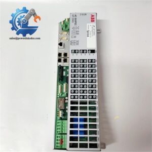
- Model: 500CIM05 (1MRB150077R1B)
- Brand: ABB
- Series: Procontrol 500 Series / P13 P14 Automation System
- Core Function: Bridges local processing units and system bus for real-time industrial data exchange
- Type: Communication Interface Module
- Key Specs: 24V DC operating voltage, industrial EMI resistance, dedicated bus signal synchronization
- Condition: New Surplus, non-refurbished, full factory physical integrity
- Status: ⚠️ Discontinued factory production, limited stock available
Product Introduction
Unstable bus communication will trigger frequent system timeout alarms in power and process control systems. The ABB 500CIM05 1MRB150077R1B solves this pain point by serving as the core data bridge for Procontrol P13 and P14 rack-based control systems. It connects local logic units with the central system bus to maintain continuous data interaction across industrial control racks.
This module delivers stable deterministic communication for high-availability industrial scenarios. It features upgraded hardware noise immunity compared with older revisions, effectively reducing data packet loss under strong electromagnetic interference. Field verified, it supports long-cycle continuous operation and keeps signal synchronization accuracy steady for power plant and substation control loops. No redundant system lag occurs during peak data transmission periods.
Key Technical Specifications
| Parameter Item | Technical Value |
|---|---|
| Full Model Code | 500CIM05 / 1MRB150077R1B |
| Applicable System | ABB Procontrol P13, P14 Automation System |
| Operating Voltage | 24V DC (internal system power supply) |
| Module Weight | 0.92 kg |
| External Dimension | 190 mm × 40 mm × 225 mm |
| Mounting Method | Plug-in installation for P13 standard sub-racks |
| Interface Type | Multi-pin backplane dedicated bus interface |
| Indicator Definition | Power, Bus Active, Fault LED status display |
| Core Feature | Deterministic bus communication, signal synchronization |
| Environmental Grade | Industrial grade, high temperature and EMI resistant |
| Origin | Switzerland |
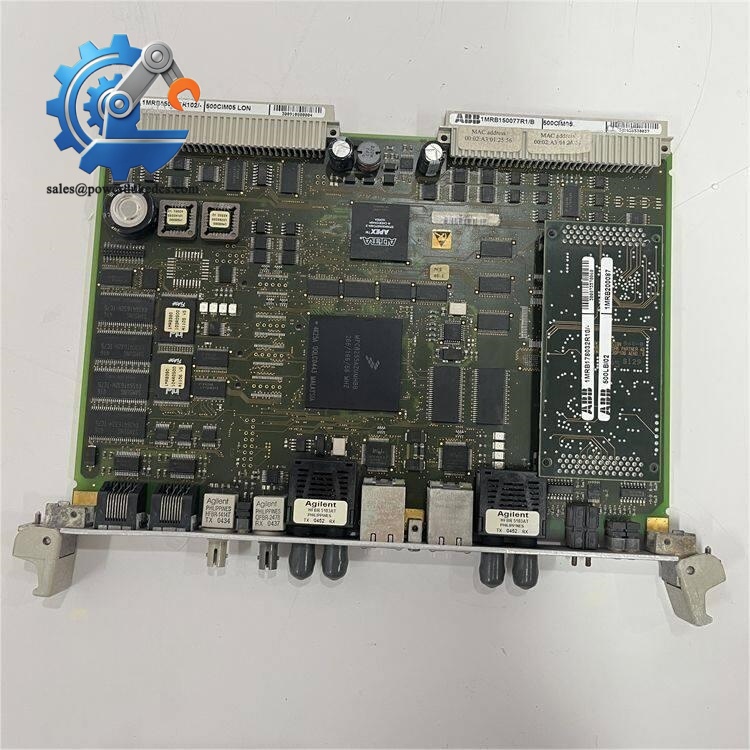
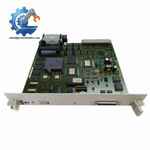
ABB 500CIM05 1MRB150077R1B
Installation & Configuration Guide
Stage 1: Pre-Installation Preparation (10 mins)
⚠️ Safety operations take priority for all rack module replacement work.
Notify the production team of scheduled downtime. Switch all field control loops to safe states, including valve locking and motor shutdown. Cut off the entire control rack power and UPS power supply. Wait 5 minutes for internal capacitor discharge to finish before any operation.
Prepare standard tools: PH1 cross screwdriver, anti-static wristband and mat, multimeter, label marker and mobile phone for configuration recording.
Complete system backup: Export the current running program to USB and cloud storage. Take clear photos of the old module’s jumper settings, backplane connection status and overall rack layout for configuration replication.
Stage 2: Old Module Removal (8 mins)
Release the front panel buckle and remove the outer protective cover. Mark each cable terminal number with labels to avoid misconnection during reinstallation. Loosen terminal screws counterclockwise and pull out cables gently without excessive force.
Press down the bottom rail buckle with a flat screwdriver. Pull the module vertically outward to separate it from the backplane connector. Check backplane pins for bending or dust accumulation; clean residual dust with compressed air if needed.
Save all configuration labels on the old module before removal. Do not damage the guide rail or backplane structure during disassembly.
Stage 3: New Module Installation (10 mins)
Wear anti-static equipment before unpacking the new module. Confirm the full model 500CIM05 1MRB150077R1B matches the replacement requirement.
Replicate the original hardware address and bus termination settings strictly according to reserved photos. This module relies on hardware jumpers for station address configuration; inconsistent settings directly cause bus conflict failures.
Align the module with rack guide rails, insert vertically and press firmly until the buckle clicks into place. Restore all labeled cables and fasten terminal screws with moderate torque. Check the module is flush with adjacent devices without tilt.
Self-check before power-on: Confirm jumper settings correct, all cables fixed, module locked firmly and no tools left inside the rack.
Stage 4: Power-On & Functional Testing (12 mins)
Test the 24V DC power supply with a multimeter to ensure voltage within standard range and no short circuit between power and ground terminals.
Power on the control rack alone first. Observe LED status: steady green light means normal power-on and standby; flashing bus light indicates ongoing data transmission; red light represents hardware or configuration faults.
Connect ABB professional configuration software to scan network devices. Verify the new module is online and consistent with system address parameters. Download the pre-backed-up program and enter system RUN mode.
Simulate system bus data interaction and check communication status with upper computer SCADA. Maintain continuous operation for over 30 minutes with no alarms. Record module serial number and replacement time in equipment maintenance logs.
Common troubleshooting tips: Communication failure mostly comes from incorrect bus termination or address conflict; persistent fault light usually results from mismatched hardware configuration.
Strict Quality Inspection SOP
All stocked ABB 500CIM05 1MRB150077R1B modules pass full-process testing before delivery to eliminate hidden risks of stock spare parts.
1. Warehouse Incoming Inspection
We verify original factory packing lists and official customs documents for source traceability. Check serial number authenticity via ABB official query channel. Conduct full appearance inspection: no corrosion, scratch, aging yellowing or disassembly traces. Complete accessories including factory certificate and specification documents are fully checked and recorded.
2. 24-Hour Live Load Test
Modules are tested on a standard ABB Procontrol P13 test rack. Complete power-on self-test, bus handshake communication and full-cycle data transmission simulation. We record real-time temperature rise during 24-hour continuous load operation to confirm stable hardware status. Complete formal test reports for each unit.
3. Electrical Performance Testing
We use Fluke 115 multimeter and 500V megohmmeter for testing. Insulation resistance is kept above 10 MΩ with qualified ground continuity performance. All electrical indexes comply with factory standard parameters.
4. Hardware Configuration Verification
Record factory default hardware version and jumper configuration status. Take photos for file backup to support customer field configuration reference.
5. Final QC & Packaging
Specialist inspectors confirm all test items pass. Modules are sealed in anti-static bags, wrapped with bubble film and packed in cartons with QC Passed labels and inspection dates. Test videos and photos can be provided upon customer request.
Field Pitfall Avoidance Guide
Years of on-site maintenance experience shows most module replacement failures come from trivial operational errors, not product quality problems.
1. Bus Address Jumper Setting Errors (Highest Failure Rate)
Factory default jumper addresses do not match most on-site system configurations. Many engineers directly power on after replacement without modification, causing entire rack bus communication paralysis.
We have encountered a substation project where unadjusted jumpers led to 4 hours of system communication failure. Always photograph and replicate old jumper positions before disassembly. Never rely on experience for blind setting.
2. Missing Bus Termination Resistance Configuration
The 120Ω bus termination resistance only needs enabling at two ends of the entire bus segment. Repeated enabling or missing setting will cause signal reflection and data packet loss.
This mistake easily causes intermittent system jitter, which is hard to troubleshoot in the short term.
3. Static Damage Without ESD Protection
Communication interface modules have sensitive internal chips. Dry winter air raises static electricity risks sharply. Unprotected direct contact can break internal circuit lines invisibly.
We have seen cases of brand-new modules burning out immediately after power-on due to no anti-static measures. Wear anti-static wristbands and operate on anti-static mats unconditionally.
4. Backplane Pin Damage From Improper Installation
Forced skew insertion will bend backplane pins, leading to poor contact or permanent module scrapping. The P13 rack has strict anti-reverse insertion design, but misalignment force still causes hardware damage.
5. Ignoring Discontinued Model Lifecycle Matching
Well, technically this module is EOL factory discontinued. Some new system firmware versions no longer fully adapt to R1/B hardware revisions. Confirm your host system version before purchasing to avoid compatibility mismatch.
Master these points, and you can avoid over 90% of on-site replacement rework and extended downtime.
Frequently Asked Questions (FAQ)
1. Can the ABB 500CIM05 1MRB150077R1B support hot swap?
It cannot support hot swap under standard P13 system operating status. Live plugging and unplugging will trigger local bus crash, resulting in offline failure of all modules in the rack. Complete power-off discharge is mandatory before replacement.
2. Is this module fully compatible with old Procontrol P13 racks?
Yes. This R1/B revision maintains full pin-to-pin compatibility with legacy P13 rack backplanes. It also upgrades EMI anti-interference performance compared with older versions, delivering more stable operation in industrial high-noise environments.
3. Do I need to brush new firmware after installation?
No extra firmware flashing is required for basic communication functions. Core protocols are solidified in onboard ROM. Only system address mapping and bus parameters need configuration via upper computer software according to on-site requirements.
4. What does a flashing Bus Active LED indicate?
A flickering bus light means the module is normally receiving and sending system bus data. A steady off status indicates bus disconnection or address conflict; a red fault light represents hardware abnormality or parameter mismatch.
5. What warranty and after-sales support can I get?
All our stocked units come with a 12-month warranty. We provide original test reports, on-site installation guidance and remote technical troubleshooting support. The listed price is for reference only, and final deals support market-based negotiation.
6. Why choose this discontinued original module instead of substitutes?
Most substitute modules fail to match the original deterministic communication timing of P13/P14 systems. Old industrial power and grid control equipment has strict protocol matching rules. Original spare parts avoid hidden system operation risks caused by adaptation gaps.



 Start Chat


