

Description
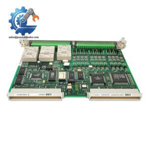
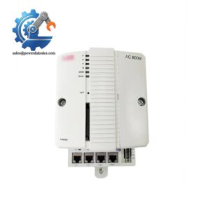
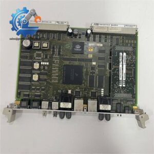
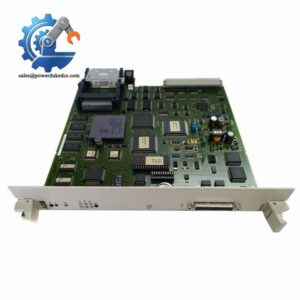
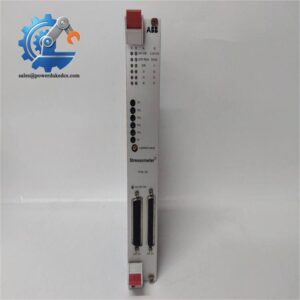
ABB AC800PEC PPD513A-23-111615 Power Excitation Control Module
SEO Titles
1. ABB PPD513A-23-111615 | AC800PEC Excitation Control Processor Module, In Stock
2. ABB AC800PEC PPD513A-23-111615 | 50/60 Hz Generator Excitation Regulation Unit
3. PPD513A-23-111615 ABB | New Surplus Power Control Module, 12-month Warranty
4. ABB PPD513A-23-111615 | Direct Replacement Module for Power Generation Excitation Systems
5. ABB AC800PEC Module PPD513A-23-111615 | On-site Buffer Stock for MRO Maintenance
Product Core Brief
-
Model: PPD513A-23-111615
-
Brand: ABB
-
Series: AC800PEC Power Electronic Control Series
-
Core Function: Regulates generator excitation output and stabilizes grid operational parameters
-
Type: Power Excitation Control Processor Module
-
Key Specs: 50/60 Hz adaptive frequency, wide temperature tolerance, real-time electrical parameter monitoring
-
Condition: New Surplus, non-refurbished
⚠️ Mature legacy power control module with stable performance; factory lead time varies significantly, on-site buffer stock recommended for power plant MRO.
Product Introduction
Unstable excitation regulation directly triggers generator voltage fluctuation and grid connection faults in power generation units. The ABB PPD513A-23-111615 serves as the core control unit for AC800PEC power electronic systems, dedicated to generator excitation closed-loop regulation.
This module collects real-time voltage, current and frequency signals from generator terminals and outputs precise excitation adjustment commands. It supports adaptive operation for 50 Hz and 60 Hz grid environments, with operational stability verified in decades of on-site power plant applications. Its wide ambient temperature adaptability cuts field failure risks caused by cabinet temperature changes. Most intermittent grid stability alarms in old excitation systems trace back to aging control core components like this module.
Key Technical Specifications
|
Parameter
|
Specification
|
|---|---|
|
Full Model Number
|
PPD513A-23-111615
|
|
Applicable System
|
ABB AC800PEC Power Control System
|
|
Functional Type
|
Generator Excitation Regulation Control Core
|
|
Adaptable Grid Frequency
|
50 Hz / 60 Hz
|
|
Operating Temperature Range
|
-25 °C ~ +70 °C
|
|
Relative Humidity
|
5% – 95% RH, non-condensing
|
|
Monitoring Parameters
|
Voltage, current, frequency, power factor, temperature
|
|
Mounting Dimension
|
125 mm × 100 mm × 80 mm
|
|
Input Signal Type
|
Field analog sensor signals
|
|
Output Control Signal
|
Excitation regulation pulse signal
|
|
Application Scenarios
|
Thermal power, hydropower generator excitation control
|
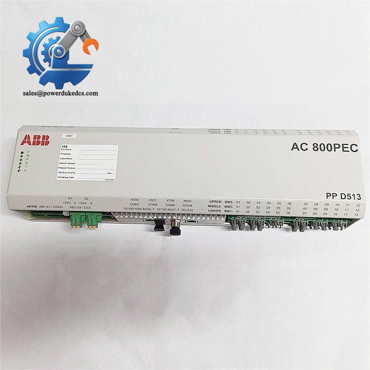
ABB AC800PEC PPD513A-23-111615
Quality Inspection SOP (Full Transparent Testing Process)
All stocked modules undergo strict multi-stage testing before delivery to eliminate hidden quality risks of surplus spare parts.
1. Warehouse Receiving Verification
We verify original factory packing lists and serial number traceability records. Inspect full appearance for no scratches, no corrosion, no component aging and no disassembly marks. Complete accessory inspection including factory certificates and specification documents.
2. Live Bench Functional Testing
Testing is completed on a standard ABB AC800PEC simulation test bench. We power on the module to check LED startup status and self-diagnosis codes. Conduct full-range signal simulation for excitation feedback and regulation output. Run continuous 24-hour aging tests to monitor temperature rise and operational stability. Complete communication handshake verification with upper control software.
3. Electrical Performance Testing
We use a Fluke 115 multimeter to complete 500V insulation resistance testing, with all test data above 10 MΩ. Perform continuity testing for internal circuits and peripheral terminals to rule out open circuit and short circuit risks.
4. Firmware & Configuration Verification
Read and record the original factory firmware version of PPD513A-23-111615. Backup default system configuration parameters and terminal definition photos for customer reference. No unauthorized firmware modification is performed.
5. Final QC & Packaging
Professional QC personnel confirm all test items pass. Seal the module in anti-static packaging, wrap with bubble film and pack in dedicated cartons. Paste QC Passed labels with test dates. Test videos and photos can be provided upon customer request.
Installation & Configuration Guide
Pre-Installation Preparation (12 mins)
⚠️ Core safety rules must be followed strictly.
Schedule formal equipment shutdown and lockout-tagout procedures. Switch off excitation system auxiliary power and main grid connection. Wait no less than 10 minutes for internal capacitor discharge. Export and backup all system control parameters and excitation logic programs.
Prepare ESD wrist strap, anti-static mat, PH1 screwdriver, digital multimeter and mobile phone for configuration photo recording.
Old Module Removal (15 mins)
Label all signal cables and power terminals one by one before disassembly. Disconnect low-voltage signal lines first, then cut off auxiliary power wiring. Release module fixing screws and pull the module vertically outward.
Inspect rack backplane connectors for pin bending, oxidation or burn marks. Photograph original wiring and terminal layout for reinstallation reference.
⚠️ Do not tilt or twist the module during removal; improper force may damage internal precision circuits.
New Module Installation (18 mins)
Wear complete ESD protection before unpacking. Confirm the full model number matches the required spare part. Copy all original terminal wiring and configuration settings strictly per recorded photos.
Align the module with the rack slot and insert vertically, tighten fixing screws evenly. Reconnect all signal and power cables in original sequence.
Pre-power checklist: All cables fixed firmly, no loose strands, module fully locked, no foreign objects left in the cabinet.
Power-On & Functional Commissioning (35 mins)
Verify input power voltage meets standard range with no short circuit risks. Restore auxiliary power and observe module self-check status.
Connect upper computer software to read module firmware version and hardware status. Download backup excitation control parameters and run system initialization.
Simulate generator load changes to test excitation regulation response accuracy. Run 30-minute continuous no-load operation with no system alarms.
Record module serial number and replacement time in equipment maintenance logs after stable operation.
On-site Replacement Pitfall Guide (Engineer Practical Experience)
1. Firmware Version Mismatch Fault
Old field systems running long-term aging firmware will trigger regulation delay or communication timeout if matched with new factory firmware. We once resolved a site fault where excitation system failed to track grid frequency after module replacement, caused by 0.2-version firmware difference.
Solution: Record original firmware version before replacement; confirm version consistency with suppliers before delivery.
2. Terminal Wiring Definition Confusion
Similar series modules have inconsistent pin definitions, leading to reversed signal input and failed excitation adjustment. Never rely on empirical wiring.
Solution: Photograph old module terminals in full detail; strictly compare with official wiring diagrams before wiring.
3. Ignored Cabinet Power Margin
Multiple control modules working simultaneously may exceed cabinet power load, causing intermittent module restart. Most users overlook this hidden risk.
Solution: Calculate total cabinet power consumption before replacement, reserve 20% power margin.
4. Neglected ESD Protection
Dry winter air brings high static electricity. Unprotected direct contact can break down internal chip circuits. We have seen field modules burn out instantly after power-on due to static damage.
Solution: Mandatory ESD operation for all disassembly and installation steps.
Frequently Asked Questions (FAQ)
Q: Can PPD513A-23-111615 support hot swap during system operation?
A: Hot swap is not allowed. Live disconnection will interrupt excitation control logic, causing generator voltage out of control and grid fluctuation. Full power shutdown is mandatory for replacement.
Q: Do I need to recalibrate parameters after module replacement?
A: Parameter backup from the old module can be directly imported. Minor excitation fine-tuning may be required according to real-time grid operating conditions to ensure optimal regulation accuracy.
Q: What are the typical failure symptoms of a faulty module?
A: Common faults include unstable generator terminal voltage, frequent excitation adjustment alarms, failed grid connection synchronization, and unresponsive load change tracking.
Q: Is this module compatible with all AC800PEC systems?
A: It matches standard AC800PEC excitation control cabinets. Send your on-site system program version and cabinet model to confirm full compatibility before ordering.
Q: What conditions void the product warranty?
A: Warranty excludes damage from static shock, incorrect wiring, overvoltage surge, humid condensation, physical extrusion damage and unauthorized disassembly. All modules pass full bench testing before shipment.
Q: What stocking strategy is suitable for this module?
A: As a critical slow-moving core power component, maintain 1 unit on-site buffer stock to avoid long factory lead-time stock-outs. Adopt vendor consignment inventory to reduce capital carrying costs.



 Start Chat


