

Description
Product Core Brief
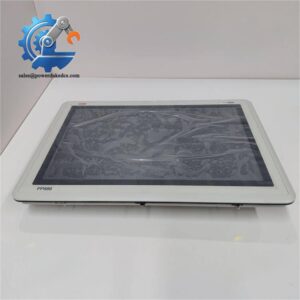
- Model: PP865A
- Part Code: 3BSE042236R2
- Brand: ABB
- Series: Panel 800 (IndustrialIT)
- Core Function: Process data display, parameter setting, alarm management, local operation for System 800xA / AC800M controller
- Type: Industrial Touch Operator Panel (HMI)
- Key Specs: 10.4 inch color TFT touchscreen, Windows CE system, built-in Compact Flash slot, multi communication interface
- Condition: New Surplus, original factory intact, non-refurbished
⚠️ Discontinued legacy HMI, limited safety stock for plant MRO replacement
Product Introduction
Key Technical Specifications
| Parameter Item | Technical Specification |
|---|---|
| Model Number | PP865A |
| Material Code | 3BSE042236R2 |
| Display | 10.4″ Color TFT LCD, Touch Screen |
| Operating System | Windows CE .NET |
| Processor | Intel XScale RISC CPU |
| Memory | RAM 64MB, Flash 32MB, External Compact Flash expansion slot |
| Power Supply | 24 VDC |
| Communication | Ethernet, RS232, RS485, Optional Profibus DP module |
| Installation Mode | Cabinet panel mounting |
| Operating Temperature | -20 ℃ ~ +60 ℃ |
| Storage Temperature | -40 ℃ ~ +70 ℃ |
| Supported System | AC800M, System 800xA IndustrialIT |
| Configuration Tool | ABB Control Builder / Panel Builder |
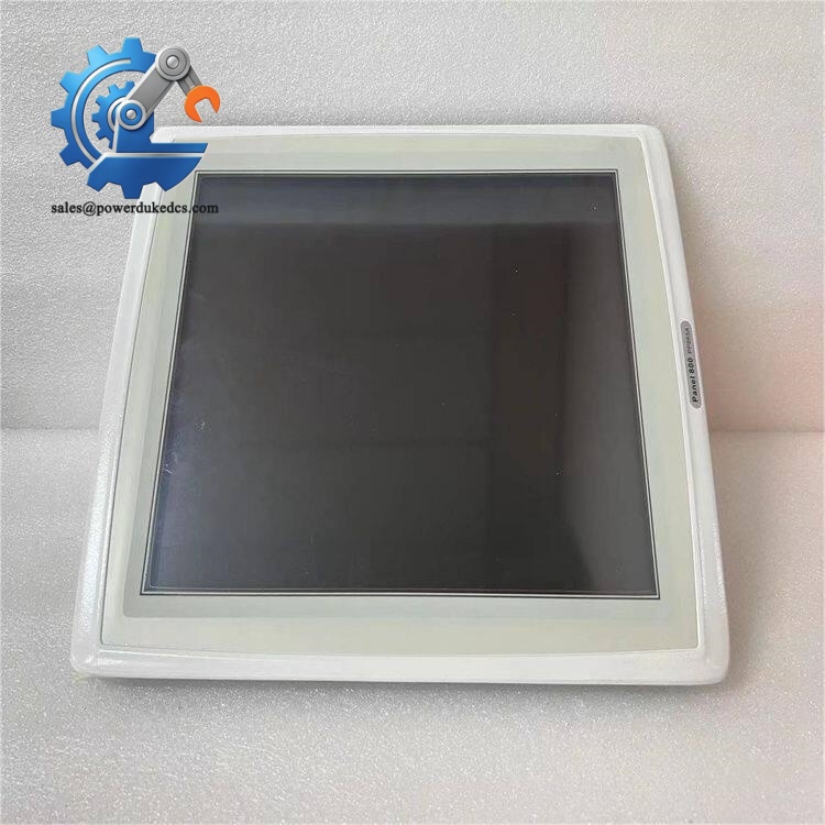
ABB PP865A 3BSE042236R2
Installation & Configuration Guide
Stage 1: Pre-Installation Preparation (12 Minutes)
Arrange equipment maintenance window, confirm related control loop operation risk. Disconnect power and wait 5 minutes for internal capacitance discharge.
Stage 2: Old Unit Removal (10 Minutes)
Remove panel fixing screws, pull out the operator panel. Check rear connector pins for oxidation and deformation. Clean cabinet installation frame dust with dry compressed air. Keep backup project file properly.
Stage 3: New Unit Installation (15 Minutes)
Install the panel into cabinet cutout and lock mounting bolts. Restore all wiring strictly according to marks. Check short-circuit risk of power terminals.
Download backup project via Panel Builder software, verify communication parameters, IP address and alarm configuration. Complete self-inspection to confirm no loose wires.
Stage 4: Power-On & Commissioning (20 Minutes)
Switch on DC power, observe panel self-test process and screen startup status. Connect engineering software to confirm communication with AC800M controller.
Check all picture windows, real-time data, alarm function and local operation buttons. Simulate fault signal to test alarm pop-up and recording function. Continuously run over 60 minutes without abnormal restart or communication dropout. Record serial number and replacement information in maintenance log.
Standard Quality Inspection SOP
Carry out source traceability inspection first, verify serial number and original factory label. Visual inspection confirm housing without scratch, corrosion or disassembly traces.
Electrical test includes power supply withstand test and insulation inspection. Firmware version and hardware revision are fully recorded.
Qualified products are packed with anti-static shielding, attached QC pass label. Test records can be provided upon customer request.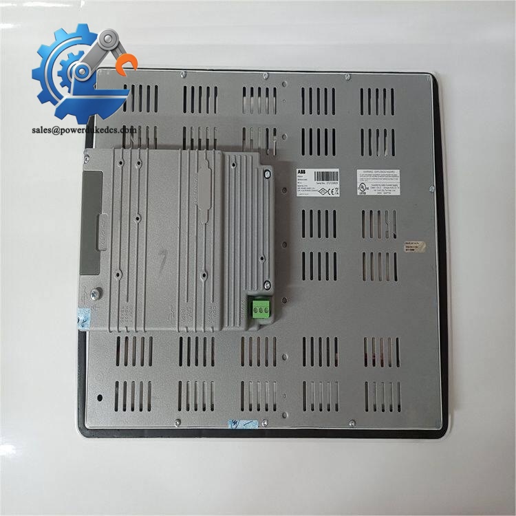
Field Replacement Pitfall Guide
Different PP865A hardware revisions have compatibility limits for project files. Directly download old projects may cause screen picture display abnormality or communication failure. Confirm firmware version consistency before downloading.
New panel restores factory default parameters. If IP address is not modified before online, network conflict will lead to original system communication anomaly. Copy IP and station address from old equipment strictly.
Touch control board and communication chip are sensitive to static electricity. Dry industrial environment increases hidden damage risk. All disassembly and wiring must use ESD protection.
Historical alarm records, trend data are stored in CF card. The data cannot be automatically migrated to new panel. Take out CF card from old equipment for data backup before removal.
If the screen display darkens, confirm whether it is backlight aging or internal power supply fault. Do not blindly replace the whole panel; separately test power supply circuit first.
Frequently Asked Questions (FAQ)
Hardware outline and installation size are consistent, but part suffix and firmware version need confirmation. Must re-download project and verify communication after replacement.
Hot swap is not recommended. Unexpected power-off will cause temporary loss of local operation function; arrange maintenance outage for replacement.
We keep limited emergency spare stock for DCS maintenance. Goods can be shipped within 1–3 working days. All units enjoy 12-month industrial warranty and remote configuration support.
Common symptoms: No display after power on, touch failure, frequent communication interruption, automatic restart, backlight cannot light up, file system error unable to load project.
Yes. We provide pre-shipment test records. Technical team offers remote guidance for project download, IP configuration and controller communication debugging.
HMI only serves as monitoring terminal; hardware replacement will not change controller program and control logic. Only local operation function will be interrupted during replacement.



 Start Chat


