

Description
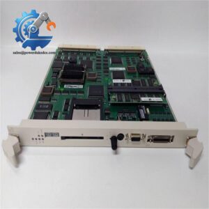
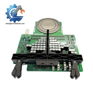
- ABB UFC718AE101 HIEE3009936R0101 | Power Stack Monitoring Module for Utility & Industrial Power Conversion
Product Core Brief
- Model: UFC718AE101
- Brand: ABB
- Part Code: HIEE3009936R0101
- Series: Power Electronics Control PCB Assembly
- Core Function: Transmit isolated gate trigger pulses and monitor power semiconductor operating status
- Type: Gate Firing / Main Circuit Interface Printed Circuit Board
- Key Specs: Fiber optic communication; Onboard isolated power supply; Hardware protection logic
Condition: New Surplus, non-refurbished
⚠️ ABB terminated original serial production; available spare inventory is limited for maintenance retrofit projects
Product Introduction
Key Technical Specifications
| Parameter | Specification |
|---|---|
| Model Identifier | UFC718AE101 |
| Assembly Part Number | HIEE3009936R0101 |
| Primary Application | Medium voltage drive, SVC power electronic control |
| Signal Transmission | Fiber optic interface for noise isolation |
| Core Function | Gate pulse generation, power device status monitoring, hardware protection |
| Onboard Power | Isolated DC/DC auxiliary power circuit |
| Operating Ambient Temperature | -20 ℃ ~ +65 ℃ |
| Mounting Method | Rack slot installation inside converter cabinet |
| Protection Class | IP00, indoor cabinet installation only |
| Compatible Equipment | ABB ACS1000 series MV drives, Static Var Compensator systems |
| ESD Sensitivity | High; mandatory anti-static handling |
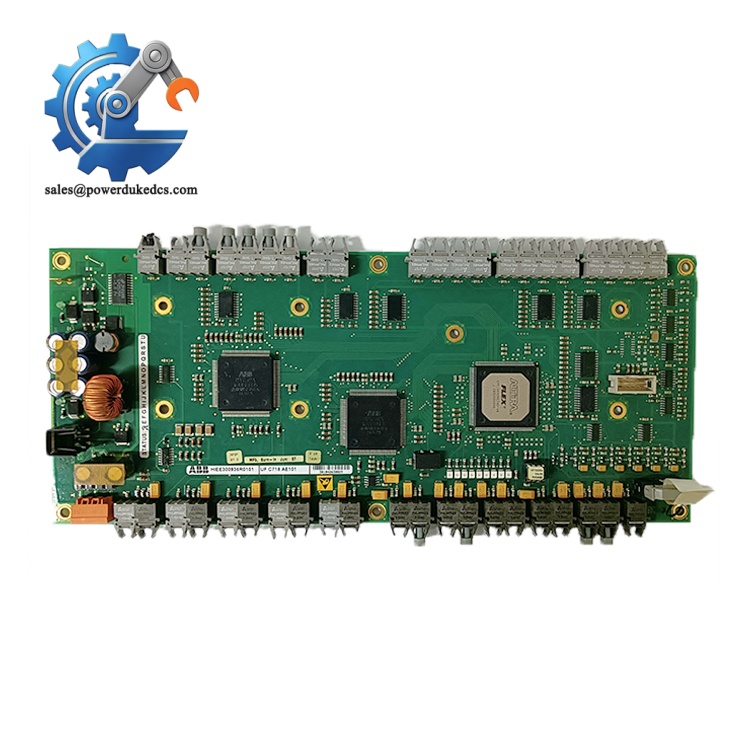
ABB UFC718AE101 HIEE3009936R0101
Installation & Configuration Guide
Phase 1: Pre-Installation (Estimated 20 min)
- Schedule complete equipment shutdown and implement lockout-tagout procedures
- Disconnect all AC input power and DC auxiliary supplies
- Maintain minimum 10-minute waiting period to discharge high-voltage DC bus capacitors
- Strict ESD protection required for all PCB handling
- ESD wrist strap and anti-static work mat
- PH1 cross screwdriver
- Fluke digital multimeter
- Mobile phone for capturing wiring and fiber routing layout
- Record original board firmware version if accessible
- Take clear photos of fiber optic cable routing and terminal wiring
- Document the exact slot position of the existing board inside the cabinet rack
Phase 2: Old Board Removal (Estimated 16 min)
- Confirm all power circuits are fully isolated
- Carefully detach fiber optic jumpers; do not bend fiber cables below minimum bending radius
- Loosen captive mounting screws on the board front panel
- Pull the board straight outward along rack guide rails
- Inspect backplane connectors for oxidation, bent pins or carbon traces
Phase 3: New Board Installation (Estimated 22 min)
- Wear anti-static gear before removing UFC718AE101 from anti-static packaging
- Visual inspection: Check PCB surface for scratches, component displacement or discoloration
- Align the board with rack guides and insert horizontally until fully seated
- Tighten front panel captive screws with moderate torque
- Reinstall fiber cables and wiring strictly following reference photos
[ ] PCB fully engaged with rack backplane
[ ] Fiber jumpers installed without sharp bending
[ ] No loose wire strands near high voltage zones
[ ] All mounting screws secured
Phase 4: Power-On & Commissioning (Estimated 35 min)
- Switch on auxiliary control power first; keep main power disconnected during initial testing
- Observe onboard LED indicators to confirm no immediate hardware fault alarms
- Connect corresponding commissioning software and verify communication links
- Complete signal loop test for gate trigger channels and feedback circuits
- Execute low-voltage system test without enabling power stack firing
- Run continuous monitoring for more than 30 minutes and check for recurring alarms
- Lost fiber communication: Inspect fiber end faces for dust contamination and check cable routing
- Persistent device fault alarm: Verify feedback signal wiring and check for damaged power semiconductors
- Unstable pulse triggering: Confirm auxiliary supply voltage stays within specified tolerance
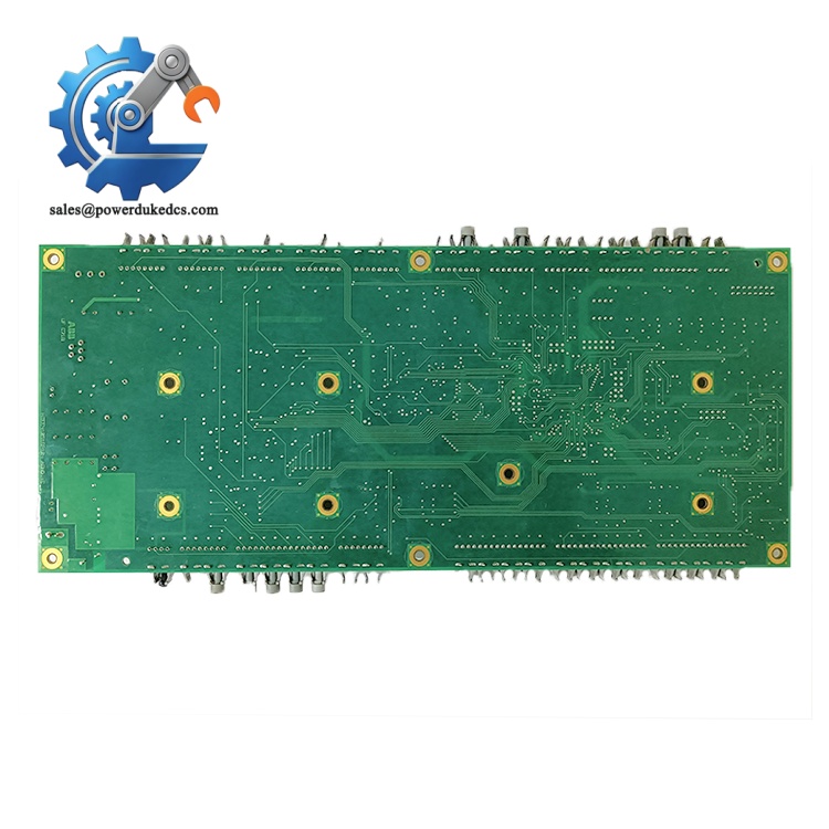
ABB UFC718AE101 HIEE3009936R0101
Frequently Asked Questions (FAQ)
-
Can UFC718AE101 directly replace UFC718AE01?
Hardware layout and component versions differ between revisions. Direct plug-and-play replacement is not guaranteed. You need to verify firmware compatibility and signal timing parameters before swapping. Multiple field cases show mismatched revisions cause random converter trips.
-
Is hot swapping allowed while the drive remains energized?
Hot swap is not supported. Removing the board cuts off all gate control signals, which will trigger immediate converter shutdown and may introduce risk to power stack components. All replacement must be performed during full equipment outage.
-
Can damaged fiber optic ports be repaired on site?
Field repair of onboard fiber transceivers is not recommended. Solder replacement requires precision workshop conditions. It is more practical to deploy a complete spare board for critical production assets.
-
What risks appear if ESD rules are ignored during installation?
The PCB contains sensitive semiconductor chips. Static discharge can cause latent damage that does not trigger immediate faults, but leads to random tripping after weeks of operation. I have witnessed one case where improper handling caused board failure 2 months after replacement.
-
Which software tool do I use for parameter checking and diagnostics?
Use the official ABB drive commissioning tool matching your ACS1000 or SVC platform. Contact technical support to confirm the software version compatible with this PCB assembly.
-
Can this board work for other brands of medium voltage converters?
This hardware is built exclusively for matched ABB power electronic systems. It cannot operate with third-party drive equipment without full custom hardware modification.
-
What warranty terms apply to UFC718AE101 HIEE3009936R0101?
We provide 12-month warranty under standard industrial operating conditions. Damage caused by incorrect wiring, high voltage surges, ESD impact, humid corrosive environments or improper mechanical handling voids warranty coverage.



 Start Chat


