

Description
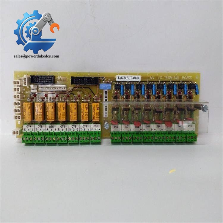
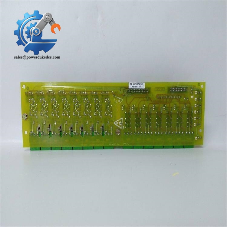
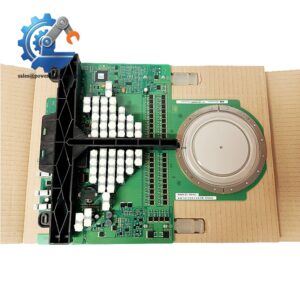
- GE 531X307LTBAFG1 | Genuine 531X Series Terminal Interface Circuit Board
Product Core Brief
- Model: 531X307LTBAFG1
- Brand: General Electric (GE)
- Series: 531X Legacy Drive Control Series
- Core Function: LAN I/O terminal board, signal conversion and wiring interface for GE drive and excitation control racks
- Type: LAN Terminal Board (LTBA)
- Key Specs: 8 universal AC/DC inputs | 7 Form C relay outputs | Built-in signal conversion circuit
- Condition: New Surplus, non-refurbished
⚠️ This board is officially discontinued by GE; global available inventory remains limited.
Key Technical Specifications
| Parameter | Specification |
|---|---|
| Full Part Number | 531X307LTBAFG1 (Alternate PN: F31X307LTBAFG1) |
| Official Name | LAN Terminal Board (LTBA) |
| Input Channels | 8 configurable universal discrete inputs, 2–240 VAC/DC |
| Output Channels | 7 Form C low-current relay contact outputs |
| Signal Conversion | Converts field AC/DC signals to standard 24 VDC logic levels |
| Diagnostic Hardware | 15 onboard status LED indicators for channel monitoring |
| Interconnection | Ribbon cable connector for backplane communication with drive control cards |
| Operating Temperature | -40 °C ~ +70 °C |
| PCB Protection | Conformal coated for dust and humidity resistance |
| Compatible Platforms | GE AC2000, DC2000, EX2000 Excitation Systems |
| Reference Document | GEI-100022B |
| Version Note | FG1 variant equipped with dedicated 24VDC input plugs; differs from later G2 revision |
Product Introduction
Application Scenarios & Pain Points
- Thermal Power Plants – Generator EX2000 Excitation Cabinets
Process field interlock signals, excitation trip commands and system status feedback for turbine generator excitation control.
- Steel Industry – Large DC Main Drives
Deployed on DC2000 drive racks for rolling mill main motors, handling speed interlocks and safety shutdown signals.
- Petrochemical Plants – Process Reciprocating Compressor Drives
Monitor local emergency stop signals and transmit drive running status to plant control room DCS.
- Mining Industry – High-power Variable Speed AC Drives
Manage equipment interlock chains for large conveyor and hoist drive systems.
A northern steel mill’s DC rolling mill drive system used the original 531X307LTBAFG1 board. After years of continuous operation, partial channel failure caused random drive trips during peak rolling load. Official supply required a 12-week lead time.
The maintenance team sourced spare board from our inventory. We completed full channel simulation testing and recorded all terminal wiring references. After delivery, technicians copied wiring one-to-one during planned maintenance. The drive resumed stable operation without unplanned downtime. This failure experience pushed the plant to reserve two spare terminal boards for critical rolling lines.
Compatibility & Replacement Matrix
531X307LTBAFG1 → 531X307LTBAFG2 : Limited compatibility; FG2 removes dedicated 24VDC input plugs; field wiring modification mandatory
531X307LTBAFG1 → Generic terminal boards : Not compatible; Unique signal conditioning and LAN communication circuit cannot be substituted
531X307LTBAFG1 → Mark V DS200 series boards : Not compatible, different rack architecture and signal logic
GE 531X307LTBAFG1
Critical Replacement Notes
- Take clear photos of all field wiring terminal assignments before removing the faulty board. Wiring mismatch causes drive lockout.
- Confirm hardware revision; FG1 and FG2 variants have different terminal layouts. Do not order blindly.
- Complete continuity testing for all input and relay output channels after installation before full load commissioning.
- Check PCB conformal coating; avoid scraping protective coating during wiring to prevent tracking faults.
Quality Control Testing Process
- Incoming Inspection
Serial number verification, visual PCB inspection. Check capacitor condition, solder joints, scratches and any repair traces.
- Power-on Live Bench Test
Install on compatible GE drive test rack, run 24-hour continuous burn-in. Simulate all 8 input channels and verify relay output switching, confirm LED diagnostic operation.
- Electrical Parameter Test
Insulation resistance test, verify signal conversion accuracy under different AC/DC input voltage ranges.
- Hardware Record
Document PCB revision, save complete channel test logs.
- Final Packaging
Seal with anti-static bag, shock-resistant bubble packaging. Test photos and inspection reports available upon customer request.
Field Installation Pitfall Guide
-
Confusing FG1 and FG2 Board Revisions
I encountered a site case where engineers purchased a G2 replacement board without checking part suffix. After installation, they found missing dedicated input terminals, spending two days redesigning field wiring. Always match the full part number including FG1 suffix.
-
Missing Wiring Documentation
Most maintenance crews remove the board without photographing terminals. Signal mix-up leads to random drive trips after replacement. Photograph every terminal connection before disassembly.
-
Static Damage During Handling
Signal processing circuits on the terminal board are sensitive to electrostatic discharge. Wear anti-static wristbands. Hidden ESD damage may only surface weeks after commissioning.
-
Overvoltage Input Damage
Field contact signals must match board rated voltage range. Improper 240VAC connected to low-voltage input channels burns onboard signal circuits instantly.
-
Ignoring Terminal Torque Specifications
Loose terminal screws create high resistance and intermittent signal loss under vibration. Torque terminals following GE wiring specification.



 Start Chat


