

Description
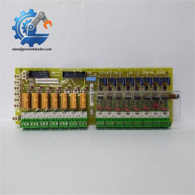
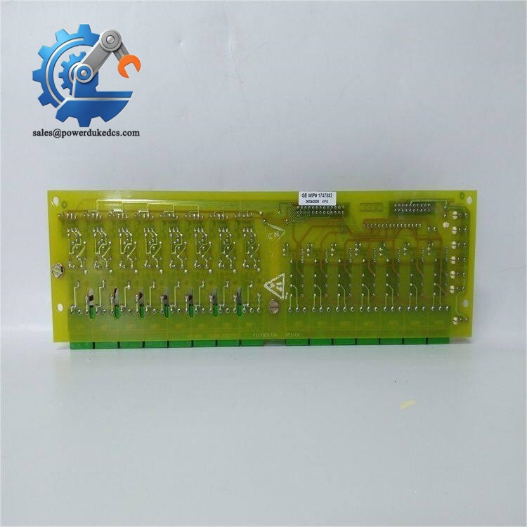
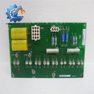
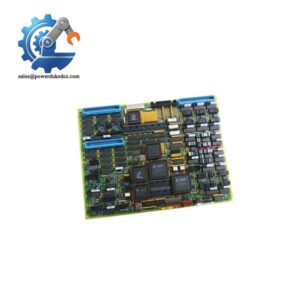
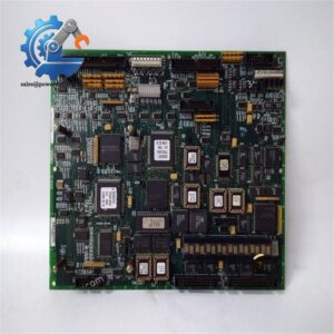
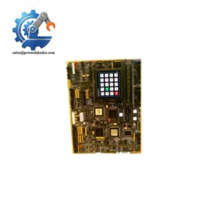
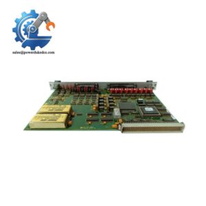
- GE 531X307LTBAKG1 | Genuine OEM 531X LAN I/O Terminal Board
Product Core Brief
- Model: 531X307LTBAKG1
- Brand: General Electric (GE)
- Series: 531X Series Control Boards
- Core Function: LAN terminal interface board, converts field signals for drive & exciter control systems
- Type: LAN I/O Terminal Board
- Key Specs: 8 universal AC/DC inputs | 7 relay outputs | Screw terminal wiring
⚠️ Discontinued original production, limited stock available
Key Technical Specifications
| Parameter | Specification |
|---|---|
| Part Number | 531X307LTBAKG1 |
| Product Type | LAN Terminal Board |
| Input Channels | 8 configurable universal control inputs |
| Input Voltage Range | 2–240 V AC/DC |
| Output Channels | 7 C-type relay outputs |
| Relay Rated Load | Up to 5 A per channel |
| Signal Conversion | Field signals converted to 24 VDC internal logic signals |
| Connection Mode | Screw terminal blocks + ribbon cable backplane interface |
| Operating Temperature | 0 °C ~ +55 °C (non-condensing cabinet environment) |
| Mounting | Cabinet standoff mounting |
| Approximate Weight | 0.35 kg |
| Origin | USA |
Product Introduction
Application Scenarios & Pain Points
- Power Generation – Generator excitation control cabinets
Process interlock signal collection and status output for generator excitation systems. Unplanned shutdown leads to huge power generation losses.
- Metals Processing – Rolling mill main drive control
Transmit run/stop interlock signals and fault alarm signals for heavy-duty rolling drives under high electromagnetic noise.
- Oil & Gas – Compressor auxiliary drive systems
Field switch signal conversion for continuous-process compression units.
- Pulp & Paper – Continuous production line drives
Stable long-term signal transmission for non-stop paper manufacturing lines.
A thermal power plant in North China encountered a fault on the original 531X307LTBAKG1 board last winter. The excitation system continuously reported interlock loss alarms. The official GE delivery lead time exceeded 12 weeks. Delaying replacement would force unit load reduction. We supplied tested surplus stock within 3 working days. After installation and wiring verification, all interlock signals returned normal, and the unit maintained full-load operation stably.
Compatibility & Replacement Matrix
531X307LTBAKG1 → 531X307LTBAFG1 : Not interchangeable; different internal LAN communication definition
531X307LTBAKG1 : No cross-brand alternative board exists; only same part number achieves direct replacement
GE 531X307LTBAKG1
Quality Control Test Procedure
- Incoming Inspection
Verify serial number traceability, inspect PCB surface for corrosion, burn marks or component aging. Check all terminal blocks, relays and connectors for intact condition.
- Visual & Continuity Test
Use Fluke 115 multimeter to check track continuity, confirm no short circuit between signal channels and power circuits.
- Power-Up Live Test
Install on dedicated 531X series test bench. Apply variable AC/DC input voltage to simulate field signals. Verify input signal conversion function and LED status indication.
- Relay Output Load Test
Test each relay channel with resistive load; check contact pull-in and release performance continuously over 24 hours. Record temperature rise of relays.
- Isolation & Dielectric Test
Insulation resistance test at 500V DC, insulation resistance target above 10 MΩ.
- Final QC & Packaging
Generate formal test report. Seal board with anti-static bag, attach QC passed label, packed with bubble cushion for shipment. Test photos or videos can be provided upon customer request.
Field Installation Pitfall Guide
Universal inputs support AC and DC, but DC signal polarity error will cause unstable signal sampling. Mark original wiring before removing the old board.
❗ 2. Ribbon Cable Interface Damage
The backplane ribbon connector is fragile. Do not pull the cable directly; hold the plastic connector shell when plugging/unplugging. Broken pins lead to intermittent LAN communication faults.
❗ 3. ESD Protection
All PCB operations require anti-static wristband. Unprotected contact can damage on-board signal chips. Dry winter environments have higher static risk.
❗ 4. Relay Load Limit
Do not connect inductive loads beyond relay rated 5A without surge suppression. Continuous overload will cause relay early burnout.
❗ 5. Cabinet Environment
Avoid installation in areas with oil mist, dust or condensation. Humidity will gradually trigger PCB trace corrosion.



 Start Chat


