

Description
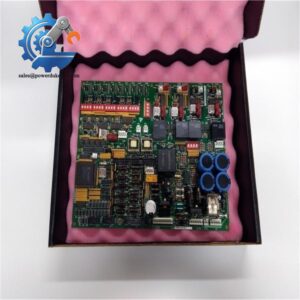
- GE DS200SIOCG1AEA | Genuine DS200 Series Turbine Control Printed Circuit Board
Product Core Brief
- Model: DS200SIOCG1AEA
- Brand: General Electric (GE)
- Series: Mark V Speedtronic Turbine Control System, DS200 hardware family
- Core Function: VME standard stand I/O board for signal collection and internal system data transmission
- Type: I/O Interface Printed Circuit Board
- Key Specs: Supports up to 33 signal wires | Onboard fuse protection | VME rack plug-in structure
- Condition: New Surplus, non-refurbished
⚠️ Original GE manufacturing discontinued, available inventory limited
Key Technical Specifications
| Parameter | Specification |
|---|---|
| Part Number | DS200SIOCG1AEA |
| Board Type | VME Stand I/O Board (SIOC) |
| Supported Signal Terminals | 5 terminal groups, maximum 33 signal wiring points |
| Onboard Hardware | 1 protection fuse, four 2-pin auxiliary connectors |
| Installation Method | Direct plug-in into standard Mark V VME rack slot |
| Supply Source | Powered through rack backplane |
| Operating Temperature | 0 °C ~ +60 °C |
| Storage Temperature | -40 °C ~ +85 °C |
| Ambient Humidity | 5%–95%, non-condensing |
| Surface Treatment | Conformal coated PCB for anti-corrosion and dust resistance |
| Approximate Net Weight | 1.0 kg |
| Applicable System | GE Mark V gas turbine, steam turbine control racks |
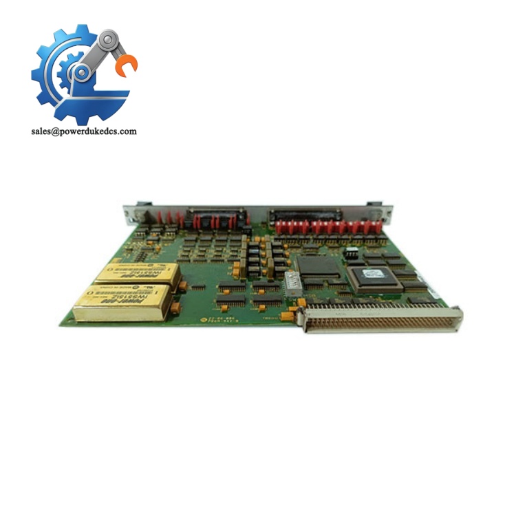
GE DS200SIOCG1AEA
Product Introduction
Application Scenarios & Pain Points
- Thermal Power Plants – Steam Turbine Mark V Control Cabinets
Process auxiliary interlock signals, valve feedback and protection discrete signals for steam turbine sets.
- Combined Cycle Power Plants – Gas Turbine Control System
Signal acquisition for gas turbine fuel control, purge sequence and vibration protection interlocks.
- Offshore Oil & Gas – On-site Power Generation Turbines
Stable signal transmission under high humidity and salt spray working environment.
- Petrochemical Plants – Process Drive Turbines
Control signal interface for large centrifugal compressor driving turbines.
- Cogeneration Plants – Waste Heat Turbine Control
Signal matching for small and medium-size turbine protection systems.
A 300MW combined cycle power plant detected unstable signal reading of auxiliary interlock loops during routine inspection. Troubleshooting confirmed aging circuit components on the DS200SIOCG1AEA board. GE official supply cycle reached 60 working days. Delayed replacement would force the gas turbine to operate under restricted monitoring conditions.
The maintenance team purchased spare DS200SIOCG1AEA from available stock. Technicians completed wiring recording, board swap and signal verification within 2 hours. All interlock signals returned to normal status. The power plant later added one spare board into critical MRO inventory.
Compatibility & Replacement Matrix
DS200SIOCG1AEA → Other DS200 series boards (DS200SLCCG1A, DS200TCCBG1B) : Incompatible, different signal definition and backplane addressing
Notice: Different hardware revisions may have minor terminal definition differences. Take photos of original wiring before disassembly.
Quality Control Process
- Incoming Inspection
Verify serial number consistency and original package information. Visual inspection to confirm no board corrosion, track damage, disassembly traces or burnt components.
- Live Bench Test
Test platform: Standard GE Mark V VME test rack
- Power-on self-test and backplane communication test
- Continuity inspection for all terminal channels
- 24-hour continuous burn-in test, monitor board temperature stability
A formal test report will be generated. Test photos or video can be provided upon customer request.
- Electrical Performance Test
500V DC insulation resistance test, insulation value ≥10 MΩ. Check onboard fuse integrity.
- Hardware Information Recording
Record board serial number and hardware revision code.
- Final QC & Packaging
Attach QC Pass label. Board sealed inside anti-static bag, packed by shockproof bubble film and export carton.
Technical Pitfall Guide for On-site Replacement
Problem: Signal channels mismatch after replacement, causing protection misoperation or signal loss.
Tip: Take clear photos for all wiring terminals before removing the faulty board. Mark wire numbers one by one.
Real case: One power station omitted wiring recording during replacement. The unit tripped unexpectedly due to misconnected interlock signal; engineers spent more than one day sorting out wiring.
Problem: Boards with different revisions have partial terminal definition changes, leading to abnormal signal collection.
Tip: Compare PCB silkscreen and revision label of old and new boards before installation.
Problem: Static electricity damages surface-mounted chips during handling, resulting in channel failure after power-on.
Tip: Wear certified anti-static wristband and operate on anti-static mat.
Problem: Dust or oxidation on backplane gold fingers causes unstable communication after board insertion.
Tip: Clean slot contacts gently before inserting new circuit board.
Problem: Scraping the PCB protective coating during installation leads to accelerated corrosion in humid cabinet environment.
Tip: Avoid hard contact on circuit board surface during transportation and installation.



 Start Chat


