

Description
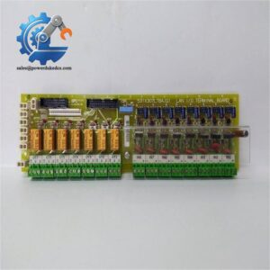
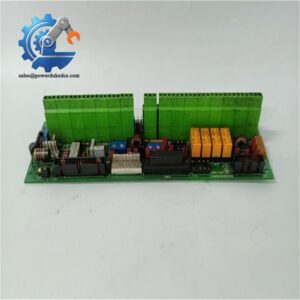
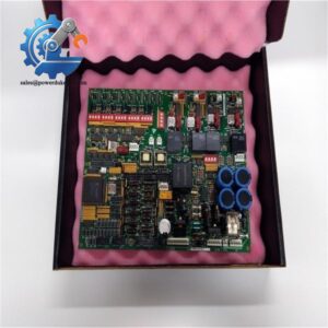
- GE DS200PCCAG5ACB | Genuine DS200 Series PCCA Turbine Control Spare Board
Product Core Brief
- Model: DS200PCCAG5ACB
- Brand: GE (GE Vernova)
- Series: Mark V Speedtronic DS200 Turbine Control
- Core Function: High-horsepower PCCA board, transmits isolated SCR gate pulses between drive control and power bridge
- Type: Power Connect Card (PCCA PCB)
- Key Specs: No onboard snubber circuits | Configurable jumpers | Conformal coated PCB
- Condition: New Surplus, non-refurbished
⚠️ Obsolete OEM legacy part, limited inventory available
Key Technical Specifications
| Parameter | Details |
|---|---|
| Full Part Number | DS200PCCAG5ACB |
| Target Platform | GE Mark V Speedtronic / DC2000 Drive System |
| Classification | High-HP PCCA (snubber circuits relocated externally) |
| Core Function | Route power circuits & deliver isolated SCR gate drive pulses |
| Configuration Components | JP1, JP2, WP3, WP4 configurable jumpers |
| PCB Protection | Industrial conformal coating against dust and humidity |
| Supported Frames | J, K, M style Mark V drive frames |
| Operating Temperature | 0 °C ~ +60 °C |
| Storage Temperature | -40 °C ~ +70 °C |
| Humidity Range | Up to 95% non-condensing |
| Mounting Method | Standard rack carrier installation inside drive cabinet |
| Interfaced Hardware | DCFB power boards, SCR excitation bridge assemblies |
| Pre-Shipment Standard | Complete live bench functional testing |
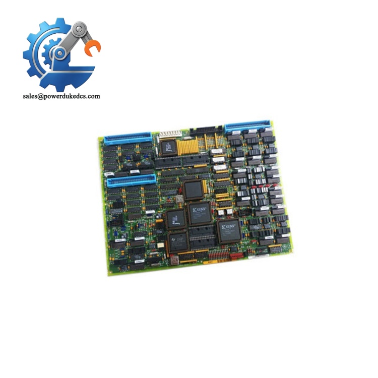
GE DS200PCCAG5ACB
Product Introduction
Application Scenarios & Pain Points
- Combined-Cycle Power Plants – Gas turbine excitation control
Designed for high-load excitation drive setups; used on large gas turbines with high continuous power output.
- Thermal Power Stations – Steam turbine generator excitation systems
Demands stable SCR pulse transmission for continuous grid-connected operation.
- Oil & Gas Cogeneration Plants – On-site power generation
Limited maintenance windows; facilities cannot sustain prolonged forced outages.
- Industrial Waste Heat Recovery Turbines – Long-cycle continuous operation
Equipment runs 24/7 with few scheduled shutdown opportunities for overhaul.
A combined-cycle power plant in East China experienced intermittent excitation alarms last winter. After troubleshooting, technicians confirmed hardware failure on DS200PCCAG5ACB. An inquiry to GE OEM returned a lead time of 16 weeks. Any prolonged shutdown would cause substantial grid supply penalties.
The plant sourced tested spare DS200PCCAG5ACB from our inventory. Before removal, engineers captured photos of all jumper positions on the faulty PCB. After replicating every configuration on the new board, replacement finished within one shift. The turbine returned to stable operation without extended downtime.
Compatibility & Replacement Matrix
DS200PCCAG5ACB → DS200PCCAG1ACB : Not directly interchangeable; different circuit design (low HP vs high HP)
DS200PCCAG5ACB → DS200PCCAG7ACB : Partial compatibility; requires full jumper rework and wiring verification
DS200PCCAG5ACB → Mark VIe PCCA boards : Not compatible, different backplane and signal definition
Quality Control SOP
- Incoming Inspection
Serial number trace verification, full visual inspection. Check PCB for corrosion, track damage, solder joint degradation, and signs of prior repair.
- Live Bench Functional Test
Test bench built with Mark V simulation hardware. Verify power continuity, pulse transformer output response and jumper switching behavior. Continuous 24-hour energized soak test.
- Electrical Performance Test
500V DC insulation resistance test, continuity check for all terminal paths.
- Documentation Retention
Record PCB revision, jumper layout photos, and full test data; photos can be provided to customers upon request.
- Final Packing
ESD anti-static sealed bag, bubble cushion protection, attached QC Pass inspection label.
Field Installation Pitfall Guide
Do not substitute DS200PCCAG1ACB for DS200PCCAG5ACB. The 5-series is built for high-horsepower drives; improper substitution creates overheating and unstable SCR triggering.
❗ Jumper Configuration Error
JP1, JP2, WP3, WP4 settings define system voltage matching. Always photograph jumper positions before removing the faulty board. Wrong settings cause excitation instability or protection trips.
❗ ESD Damage Risk
PCB components are static sensitive. Wear anti-static wristbands during handling, especially in dry winter environments. Multiple field failures originate from unprotected manual contact.
❗ Edge Connector Inspection
Check connectors for bent pins and oxidation before installation. Poor contact creates hard-to-diagnose intermittent pulse loss faults.
❗ Cabinet Thermal Environment
Ensure cabinet cooling fans operate normally. Elevated internal cabinet temperature accelerates aging of legacy conformal-coated circuit boards.



 Start Chat


