

Description
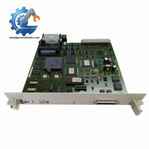
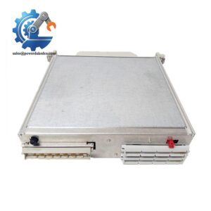
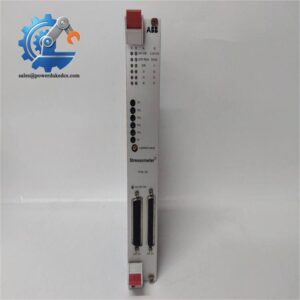
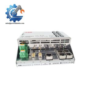
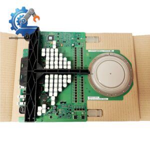
- GE 531X307LTBAKG1 | Genuine 531X Series I/O Terminal Board, Limited Inventory
Product Core Brief
- Model: 531X307LTBAKG1
- Brand: GE General Electric
- Series: 531X Series Drive & Exciter Control Boards
- Core Function: LAN Terminal Board, converts field AC/DC interlock signals to internal 24 VDC logic for drive and excitation controllers
- Type: LAN Digital I/O Terminal Interface Board
- Key Specs: 8 universal inputs (2–240 V AC/DC) | 7 Form-C relay outputs | Backplane ribbon cable connection
- Condition: New Surplus, non-refurbished
⚠️ This legacy board is officially discontinued by GE, available stock is limited.
Key Technical Specifications
| Parameter | Specification |
|---|---|
| Full Part Number | 531X307LTBAKG1 (G1 Revision) |
| Product Name | LAN Terminal Board (LTBA) |
| Compatible System | GE DC300 Drives, Mark V Generator Excitation Control Systems |
| Digital Inputs | 8 universal configurable inputs, 2–240 V AC/DC |
| Signal Conversion | Converts field signals to standardized 24 VDC logic levels |
| Relay Outputs | 7 Form-C (SPDT) low-current relay contacts |
| Logic Power Supply | 24 VDC via rack backplane, typical consumption <5 W |
| Connection Mode | Ribbon cable interconnect with main control processor / NTB board |
| Operating Temperature | 0 ℃ ~ +55 ℃, non-condensing cabinet installation |
| Relative Humidity | 10% – 90% RH |
| Protection Circuit | On-board transient surge suppression for input channels |
| Mechanical Installation | Cabinet standoff mounting, matches 531X series chassis layout |
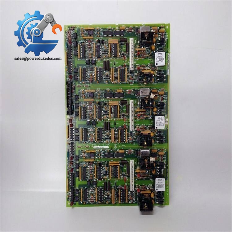
GE 531X307LTBAKG1
Product Introduction
Application Scenarios & Pain Points
- Thermal Power Plants – Generator Static Excitation Cabinets
Process generator field interlock signals, excitation startup permissives and fault status feedback for turbine-generator sets.
- Metallurgy Industry – Heavy-Duty DC Rolling Mill Drives
Collect safety interlock signals from gearboxes, cooling systems and emergency stop circuits for main DC drives.
- Oil & Gas – Turbomachinery Auxiliary Drive Control
Support auxiliary motor interlock logic for large steam and gas turbine packages.
- Pulp & Paper Industry – Continuous Production Line DC Drives
Monitor safety interlocks of paper machine main drives under continuous heavy load operation.
- Mining Industry – Large Conveyor & Hoist DC Drive Control
Handle emergency stop, door interlock and cooling system status signals.
A regional thermal power plant encountered unstable interlock signal reception on its generator excitation cabinet. Troubleshooting confirmed component aging on the original 531X307LTBAKG1.
The unit could not operate reliably with incomplete protection interlocks. Maintenance technicians installed the replacement board during a scheduled outage. After verifying all input signal conversion and relay output functions, all excitation interlock logic returned fully operational. The site added two spare LTBA boards to the MRO warehouse for emergency maintenance.
Compatibility & Replacement Matrix
531X307LTBAKG1 (G1 Revision) → Older LTBA hardware revisions : Partial compatible, full signal testing mandatory after swap
531X307LTBAKG1 → 531X305NTBAKG1 : Not interchangeable (NTBA is analog/encoder board; LTBA handles universal digital interlock signals)
Critical Replacement Warnings
- Photograph all field wiring terminals before removing the old board. Pin assignment mismatches will cause interlock failures.
- Disconnect all rack power and field external power before board replacement to avoid input channel burnout.
- Confirm input signal AC/DC type during commissioning; improper wiring may damage onboard signal conditioning circuits.
- Perform full interlock loop testing after hardware replacement to verify all logic operates as designed.
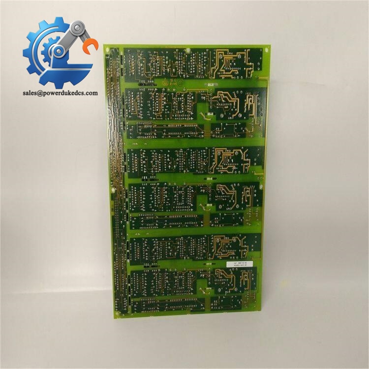
GE 531X307LTBAKG1
Quality Control Process
- Incoming Inspection
Verify complete part number labeling, serial traceability and PCB physical condition. Inspect for corrosion, scratches or disassembly traces.
- ESD Control
All testing and storage work is completed on anti-static workbenches with anti-static wristbands.
- Bench Functional Live Test
Mount board on matched GE DC300 / Exciter test rack. Simulate 2–240 V AC/DC input signals to verify logic conversion. Test all seven relay outputs. Continuous 24-hour aging test.
- Electrical Parameter Testing
Check channel insulation resistance, surge protection circuit integrity and relay contact continuity.
- Final QC & Packaging
Generate formal test report, seal PCB with anti-static bag, wrap with bubble film. Attach QC passed label before shipment. Test photos and videos can be provided upon client request.
Module Replacement Pitfall Guide
-
Confuse LTBA and NTB Series Boards
Risk: Install wrong board, entire interlock or speed feedback system fails.
Advice: Confirm full printed part number on PCB silkscreen. LTBA = digital interlock board; NTB = analog & encoder terminal board.
Real case: A maintenance engineer mistakenly prepared an NTB board for LTBA replacement, delaying cabinet repair for half a shift.
-
Missing Wiring Reference Photos
Risk: Incorrect wiring leads to missing permissive interlocks, preventing equipment startup.
Advice: Capture clear photos of all terminal wiring before disassembly. Never rely on memory.
-
Skip Post-Replacement Signal Loop Test
Risk: Hidden channel faults remain undiscovered, triggering unexpected equipment trips after restart.
Advice: Simulate every interlock signal and confirm controller receives correct status.
-
Ignore ESD Safety Protocols
Risk: Static electricity damages signal conditioning chips, creating intermittent random interlock dropout faults.
Advice: Wear anti-static wristbands while handling bare circuit boards, especially in dry winter environments.
-
Apply Overvoltage to Input Terminals
Risk: Permanent burnout of input optocoupler circuits.
Advice: Confirm maximum field voltage does not exceed 240 V AC/DC before energizing wiring.



 Start Chat


