

Description
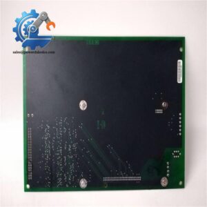
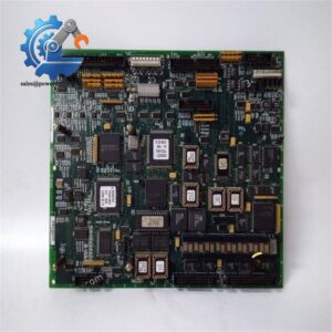
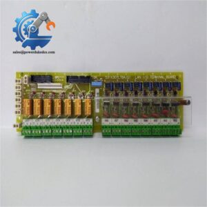
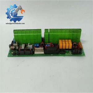
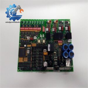
- GE DS200RTBAG3AHC | OEM RTBA Interface Board for Power Generation Turbine Systems
Product Core Brief
- Model: DS200RTBAG3AHC
- Brand: General Electric (GE)
- Series: Mark V DS200 Speedtronic Turbine & Drive Control Platform
- Core Function: Relay terminal interface board to connect control logic with field actuators and safety circuits
- Type: RTBA Relay Terminal Board
- Key Specs: 10 onboard form-C relays | 52 I/O terminal points | CPH/CPN power connectors
- Condition: New Surplus, non-refurbished
⚠️ Original manufacturing discontinued, limited available stock
Key Technical Specifications
| Parameter | Specification |
|---|---|
| Full Part Number | DS200RTBAG3AHC |
| Functional Abbreviation | RTBA (Relay Terminal Board) |
| Onboard Relays | 10 Form-C electromechanical relays (NO / COM / NC contacts) |
| I/O Terminals | 52 screw terminal points for field wiring |
| Power Interface | CPH, CPN pluggable control power connectors |
| PCB Protection | Standard conformal coating against dust and mild humidity |
| Operating Temperature | 0 °C ~ 60 °C inside enclosed control cabinet |
| Mounting Form | Cabinet rack-mounted PCB for DS200 series drive systems |
| Typical Load Application | Solenoid valves, alarm annunciators, auxiliary contactors, safety interlock circuits |
| Supported Platforms | GE Mark V gas/steam turbine control, DC2000 / AC2000 generator exciters |
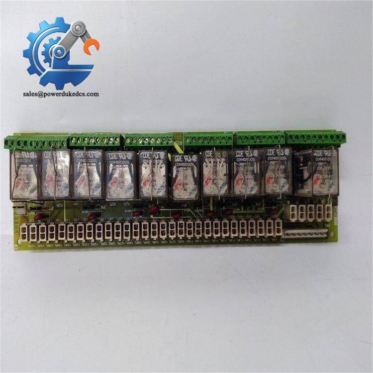
GE DS200RTBAG3AHC
Product Introduction
Application Scenarios & Pain Points
- Gas Turbine Power Plants – Mark V Frame Turbine Control
Drive fuel solenoid valves, lube oil pump interlocks and emergency trip circuit annunciators.
- Thermal Power Stations – Generator Exciter Systems
Installed within DC2000 / AC2000 exciter cabinets to control auxiliary contactor logic.
- Steam Turbine Auxiliary Control Systems
Manage condenser vacuum protection, boiler feed pump permissive and alarm signal outputs.
- Industrial Co-Generation & Cogas Facilities
Safety interlock control for packaged gas turbines and waste heat recovery units.
A coastal thermal power plant’s Mark V turbine control system reported unstable alarm signals and intermittent interlock failures. After troubleshooting, maintenance staff confirmed multiple aging relays on the original DS200RTBAG3AHC developed contact resistance drift. GE official lead time reached 11 weeks. The procurement team purchased a pre-tested spare board from available stock. Technicians took complete photos of all field terminal wiring before disassembly. After direct replacement and wiring restoration, all interlock and alarm circuits operated normally within one shift, avoiding a scheduled unit outage.
Compatibility & Replacement Matrix
DS200RTBAG3AHC → DS200RTBAG3AHC: Direct plug-and-play replacement; strictly duplicate all field wiring connections
DS200RTBAG3AHC → Non-RTBA DS200 boards (DS200DCFB series): Not compatible, different circuit function and connector layout
Critical Replacement Notes
- Document wiring layout: Take clear photos of every terminal connection before removing the board. Miswired relay contacts cause safety interlock malfunctions.
- Relay contact load limits: Do not exceed rated contact load; overcurrent accelerates relay contact burnout.
- Power lockout procedure: Disconnect all control and field power before wiring work; the board carries live high-energy circuits.
- Mandatory ESD protection: Wear anti-static wristbands during PCB handling; onboard signal circuits are sensitive to electrostatic discharge.
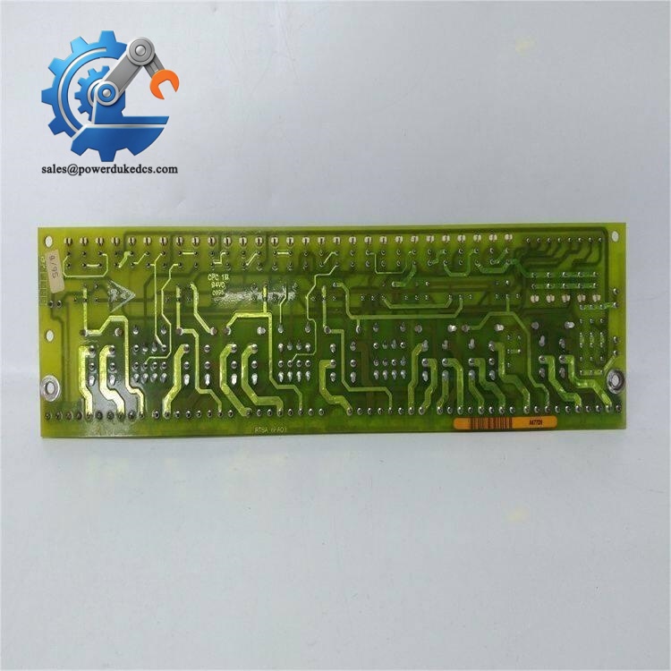
GE DS200RTBAG3AHC
Quality Control Process (Transparent Inspection Standard)
- Incoming Inspection
Serial number verification, full visual inspection for PCB corrosion, trace damage, unauthorized solder repair, relay aging or loose terminals. Check conformal coating integrity.
- Bench Functional Live Test
Mount board inside standard GE Mark V test rack. Complete power-on test, verify every relay pull-in and drop-off action. Simulate control signals to test all 10 relay channels continuously. Run 24-hour burn-in cycle. Custom test reports and inspection photos can be provided upon request.
- Electrical Parameter Testing
Relay contact continuity testing, insulation resistance test between channels.
- Hardware Recording
Document physical layout and relay default status for customer reference.
- Final QC & Packing
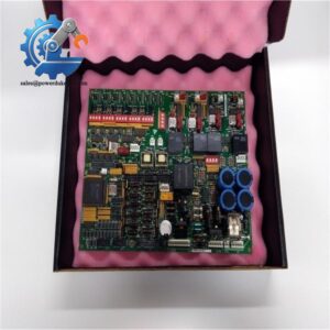
QC engineer sign-off, sealed inside anti-static shielding bag, wrapped with bubble foam. Attach QC Passed label marked with inspection date.
On-site Pitfall Guide for Engineers
- Skipping Terminal Wiring Documentation
I witnessed a site incident where technicians replaced the RTBA board without recording wiring. After power-up, safety interlock logic reversed, creating dangerous operating conditions. Always photograph all terminals before removal.
- Random Interchange of Different RTBA Revisions
Do not substitute DS200RTBAG3 variants with different suffixes. Minor PCB layout changes alter relay routing and cause abnormal equipment behavior.
- Ignoring Relay Contact Degradation
For older used boards, check relay contact resistance. Oxidized contacts generate unstable signals and random interlock trips under vibration.
- Live-Wiring Risk
Many technicians perform wiring work without full power isolation. Accidental short circuits can burn PCB traces permanently. Lock out all power sources first.
- Neglecting Cabinet Vibration Impact
Turbine cabinets have continuous vibration. Loose terminal screws create high resistance and interm



 Start Chat


