

Description
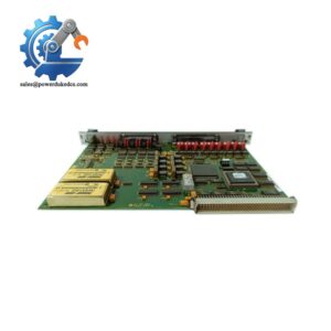
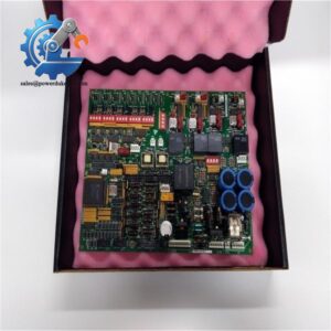
- GE DS200FSAAG1ABA | Genuine OEM Field Supply Amplifier Control Board
Product Core Brief
- Model: DS200FSAAG1ABA
- Brand: General Electric (GE)
- Series: Mark V Speedtronic Turbine Control (DS200 Series)
- Core Function: Generates and amplifies isolated gate trigger pulses for excitation SCR rectifiers
- Type: Field Supply Gate Amplifier Board (FSAA)
- Key Specs: 10-pin backplane connector | 2 built-in 600V 30A fuses | 5 configurable jumpers
⚠️ Original manufacturing discontinued, limited surplus inventory available
Key Technical Specifications
| Parameter | Specification |
|---|---|
| Full Part Number | DS200FSAAG1ABA |
| Functional Name | Field Supply Gate Amplifier Board (FSAA) |
| Compatible System | GE Mark V Speedtronic Turbine Control System |
| Interface | 1 x 10-pin backplane connector |
| Protection Components | 2 × 600 V, 30 A fuses |
| Configuration | 5 onboard configurable jumpers, multiple test points |
| Primary Function | Amplify low-level control pulses to drive SCR gate circuits for excitation regulation |
| Operating Temperature | 0 °C ~ +60 °C, non-condensing cabinet environment |
| Storage Temperature | -40 °C ~ +85 °C |
| Approximate Weight | 0.36 kg |
| Mounting Form Factor | Standard DS200 series rack-mount PCB |
| Isolation Design | High voltage isolation between control logic and power trigger circuits |
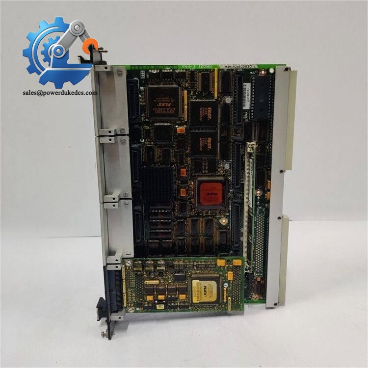
GE DS200FSAAG1ABA
Product Introduction
Application Scenarios & Pain Points
- Thermal Power Plants – Steam Turbine Generator Excitation Control
Deliver stable SCR trigger signals for generator excitation rectifier bridges. Unplanned excitation system faults directly force unit load reduction.
- Combined Cycle Power Plants – Heavy-Duty Gas Turbine Control
Work alongside Mark V rack to maintain steady generator voltage under variable grid load conditions.
- Oil & Gas Facilities – On-Site Turbine-Driven Compressors
Supports turbine speed and excitation control for remote compression stations with limited backup equipment.
- Industrial Cogeneration Plants – Self-Generation Turbine Sets
Suitable for continuous operation industrial power systems where long downtime cannot be tolerated.
A combined-cycle power station in East China encountered repeated excitation fluctuation alarms last winter. Troubleshooting confirmed the original DS200FSAAG1ABA board exhibited unstable pulse output. GE official delivery required 14 weeks. Any prolonged unit derating would create massive revenue loss.
We supplied pre-tested surplus stock within 4 working days. After physical replacement and jumper configuration matching, excitation voltage stabilized, and the unit returned to full-load continuous operation. The maintenance team later purchased one spare board to avoid similar emergency risks.
Compatibility & Replacement Matrix
DS200FSAAG1ABA → DS200FSAAG1A : Needs artwork revision confirmation; verify jumper setting before power-up
DS200FSAAG1ABA : No cross-brand equivalent substitute; same full part number is required for direct replacement
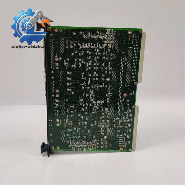
GE DS200FSAAG1ABA
Quality Control Test Procedure
- Incoming Visual Inspection
Check PCB surface for corrosion, burnt traces, cracked capacitors, or repair solder marks. Verify fuse integrity and all connector pins. Serial numbers are recorded for traceability.
- Continuity & Component Check
Use Fluke 115 multimeter to test track continuity, confirm no short circuits between signal circuits and power circuits.
- Power-Up Live Bench Test
Mount the board on dedicated Mark V DS200 test rack. Supply specified backplane voltage, monitor output trigger pulses via oscilloscope. Confirm LED status and pulse amplitude match factory specifications.
- Load Simulation Test
Simulate SCR gate load conditions, run continuous 24-hour aging test, record component temperature rise.
- Insulation Resistance Test
500 VDC megohmmeter test; insulation resistance maintained above 10 MΩ between isolated circuits.
- Final QC & Packing
Complete formal test report. Seal PCB inside anti-static bag, attach QC passed label. Package with bubble cushion for transit. Test photos or video can be provided upon customer request.
Field Installation Pitfall Guide
This board relies on 5 onboard jumpers to match site operating mode. Take clear photos of jumper positions on the faulty board before removal. Mismatched jumpers cause abnormal excitation voltage or complete trigger loss.
❗ 2. Backplane Connector Handling
The 10-pin edge connector is fragile. Do not pull the board forcibly from the rack. Bent pins lead to intermittent pulse faults that are difficult to diagnose.
❗ 3. ESD Protection Mandatory
All PCB handling must use anti-static wristbands and anti-static mats. Static discharge can damage pulse amplifier chips. Risks rise significantly during dry winter seasons.
❗ 4. Fuse Specification Compliance
Only install 600 V / 30 A specified fuses. Higher-rated replacement fuses eliminate circuit protection and may cause secondary PCB damage.
❗ 5. Cabinet Environment Control
Avoid installation in areas with oil mist, dust or condensation. Capacitor aging accelerates rapidly under high humidity, shortening service life.
❗ 6. Power Sequence
Cut full rack power before swapping the board. Hot swapping may induce voltage surges and destroy onboard semiconductors.



 Start Chat


