

Description
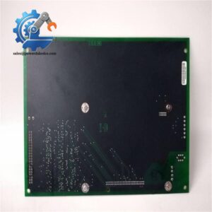
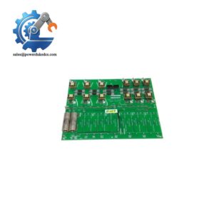
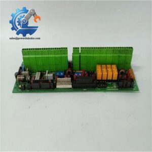
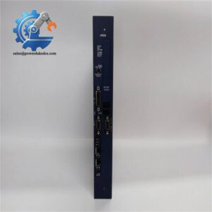
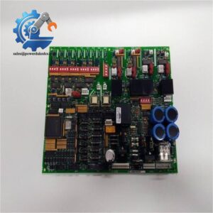
- GE DS200DCFBG1BLC | OEM DCFB Board for Power Generation Drive Control
Product Core Brief
- Model: DS200DCFBG1BLC
- Brand: General Electric (GE)
- Series: Mark V DS200 Drive Control Platform
- Core Function: DC feedback & control power supply board for GE industrial drives and exciters
- Type: DCFB (DC Feedback) Power Supply Board
- Key Specs: 38–115 VAC input | Configurable jumpers & DIP switches | Multi-channel power output
- Condition: New Surplus, non-refurbished
⚠️ Original production discontinued, limited stock available
Key Technical Specifications
| Parameter | Specification |
|---|---|
| Full Part Number | DS200DCFBG1BLC |
| Input AC Voltage Range | 38 VAC ~ 115 VAC |
| Supported Input Frequency | 0 Hz ~ 500 kHz |
| Onboard Power Outputs | +5 VDC, ±15 VDC, ±24 VDC control power; 115 VAC for cabinet cooling fans |
| Configuration Hardware | 12 configurable jumpers, 7 DIP switches |
| Protection Components | 3 onboard protective fuses |
| Diagnostic Indicators | 2 LED indicators, 1 neon fuse status lamp |
| Test Points | 5 accessible signal test points for field troubleshooting |
| Built-in Circuits | AC/DC monitoring circuit, control power circuit, motor field power circuit, driver circuit |
| Compatible Drive Series | DC2000, AC2000, CB2000, ME2000, FC2000 exciters & drives |
| Operating Ambient Temperature | 0 °C ~ 60 °C (enclosed control cabinet) |
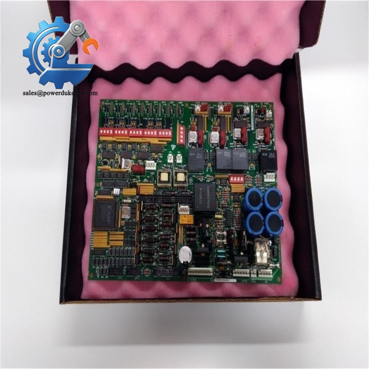
GE DS200DCFBG1BLC
Product Introduction
Application Scenarios & Pain Points
- Thermal Power Plants – Generator Exciter Control
Deployed on GE DC2000 / AC2000 exciters to maintain stable excitation power for synchronous generators.
- Combined Cycle Power Station – Auxiliary Motor Drives
Control large auxiliary drive systems for boiler fans, circulating water pumps and compressors.
- Oil & Gas Facilities – Electric Drive Compressors
Serves variable-speed DC drives for natural gas compression units under continuous heavy-load conditions.
- Heavy Industry – Metallurgy DC Motor Drives
Regulate power and feedback signals for rolling mill DC drives in steel production lines.
A coastal power plant’s 20 MW auxiliary exciter system reported unstable field current fluctuations. After troubleshooting, maintenance crews confirmed the aging DS200DCFBG1BLC developed intermittent feedback circuit faults. Original GE factory delivery required 12 weeks. The procurement team sourced a tested spare DS200DCFBG1BLC from available inventory. Engineers recorded all jumper and DIP switch positions before removing the faulty board. After hardware replacement and parameter replication, the exciter resumed stable operation within one shift, avoiding a planned unit outage.
Compatibility & Replacement Matrix
DS200DCFBG1BLC → DS200DCFBG1BLC: Direct replacement; strictly match jumper/DIP switch settings of original board
DS200DCFBG1BLC → Other DS200 series boards (DS200SDCCG1A): Not compatible, different circuit function
Critical Replacement Notes
- Preserve original configuration: Take clear photos of all 12 jumpers and 7 DIP switches before removing the faulty board. Incorrect settings cause drive misoperation or overcurrent trips.
- Input voltage verification: Confirm field AC input stays within 38–115 VAC range; overvoltage will blow onboard fuses.
- Wiring check: Verify fan power wiring and field feedback terminal connections; reversed wiring damages signal circuits.
- ESD protection: All circuit board handling requires anti-static wristbands; feedback signal circuits are sensitive to electrostatic discharge.
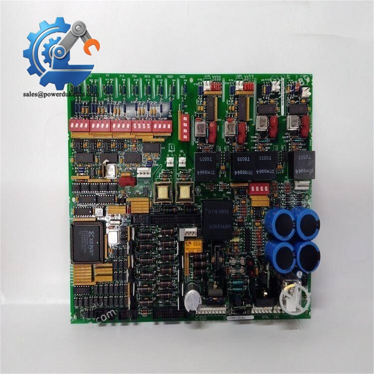
Quality Control Process (Transparent Inspection Standard)
- Incoming Inspection
Serial number verification, full visual inspection for PCB corrosion, track damage, solder rework or component aging. Check for broken connectors and capacitor bulging.
- Bench Functional Live Test
Install the board inside a GE Mark V drive test rack. Complete power-on self-test, verify all LED and neon indicators. Simulate AC input voltage and test all DC power rail outputs. Conduct continuous 24-hour burn-in test. Custom test reports and inspection photos can be provided upon demand.
- Electrical Parameter Testing
DC rail voltage measurement, insulation resistance test, fuse continuity verification.
- Hardware Configuration Recording
Document factory default jumper and DIP switch layout for customer reference.
- Final QC & Packing
QC engineer sign-off, sealed in anti-static shielding bag, wrapped with bubble foam. Attach QC Passed label marked with inspection date.
On-site Pitfall Guide for Engineers
- Ignoring Jumper & DIP Switch Records
I encountered a site case where technicians swapped the board without recording switch positions. After power-up, the drive generated field current overload alarms. Two shifts were spent to recover correct settings. Always photograph the configuration before removal.
- Confusing DS200DCFBG1 variants
Do not substitute DS200DCFBG1 for DS200DCFBG1BLC. Early hardware revisions lack updated feedback protection circuits and will trigger unstable operation.
- Skipping Pre-power Wiring Inspection
Several field failures happen because technicians forget to check fan circuit short circuits. Short-circuit loads blow the board’s internal fuses immediately after energization.
- Static Damage During Installation
The low-voltage feedback circuit has sensitive surface-mount components. In dry winter environments, static discharge can destroy signal channels without visible physical damage.
- Overlooking Capacitor Aging Risks
For used boards, check electrolytic capacitors closely. Degraded capacitors cause voltage ripple and random drive trips during load fluctuations.



 Start Chat


