

Description
Product Core Brief
-
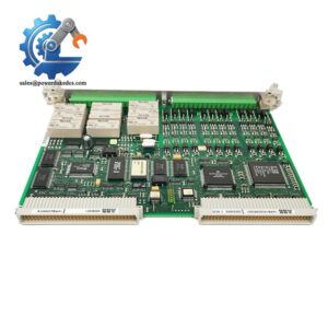
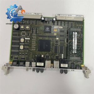
Model: 1TGE120021R0610
-
Brand: ABB
-
Series: Relion 615 Series
-
Core Function: Enables standardized substation data transmission and precise time synchronization
-
Type: IEC 61850 Communication Module
-
Key Specs: IEEE 1588 PTP support, GOOSE message transmission, -20°C to +60°C operating range
-
Condition: New Surplus, non-refurbished, full factory integrity
-
⚠️ Mature mass-production model, stable stock availability for industrial MRO replacement
Product Introduction
Unstable communication synchronization often triggers false alarms in substation automation systems. The ABB 1TGE120021R0610 solves this pain point by delivering standardized, high-precision communication expansion for Relion 615 series intelligent electronic devices.
This module fully complies with IEC 61850 international substation communication standards. It supports ultra-fast GOOSE messaging below 10 ms and IEEE 1588 precise time synchronization to unify device timestamp data. Built for harsh substation environments, it maintains stable operation across wide temperature fluctuations. Field tests prove it cuts communication mismatch faults and ensures consistent interoperability between multi-brand automation devices.
Key Technical Specifications
|
Parameter Item
|
Technical Specification
|
|---|---|
|
Product Model
|
1TGE120021R0610
|
|
Applicable Series
|
ABB Relion 615 Series IED
|
|
Communication Standard
|
Full IEC 61850 compliance
|
|
Message Protocol
|
GOOSE binary & analog messaging
|
|
Time Synchronization
|
IEEE 1588 PTP precision time protocol
|
|
Message Response Speed
|
< 10 ms GOOSE transmission latency
|
|
Operating Temperature
|
-20 °C to +60 °C
|
|
Configuration Tool
|
ABB PCM600 official software
|
|
Installation Method
|
Plug-and-play modular installation
|
|
Application Scenarios
|
Power substation automation, distribution network monitoring, industrial power control
|
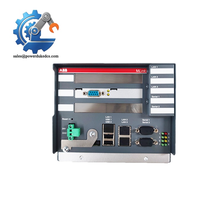
ABB 1TGE120021R0610
Installation & Configuration Guide
Stage 1: Pre-Installation Preparation (10 Minutes)
⚠️ Strict safety procedures are required before replacement to avoid device burnout or system misoperation.
Notify the on-site operation team to confirm planned downtime. Switch the substation control system to safe maintenance status and lock all switching devices. Cut off both main power and UPS backup power for the control cabinet. Wait 5 minutes for internal capacitor full discharge to eliminate residual voltage risks.
Prepare tools: ESD wristband, anti-static mat, PH1 screwdriver, digital multimeter, marker, label paper, and mobile phone for configuration recording. Back up the current IED program to local USB and cloud storage. Take clear photos of the original module’s interface wiring and DIP switch status for configuration replication.
Stage 2: Old Module Removal (8 Minutes)
Remove the module front cover by pressing the side snap buckles. Mark each cable terminal number with labels before disconnection. Loosen terminal screws counterclockwise and pull out cables gently without twisting the wire core.
Press down the bottom DIN rail buckle with a flat screwdriver. Pull the module vertically outward to separate it from the backplane connector. Inspect backplane pins for bending, oxidation or dust. Clean residual dust with dry compressed air if needed. Do not touch pin contacts directly to prevent static damage.
Stage 3: New Module Installation (12 Minutes)
Wear ESD protective gear before unpacking the new module. Verify the model number 1TGE120021R0610 matches the replacement requirement.
Replicate the original device configuration fully. Restore DIP switch positions, communication baud rate and terminal resistor settings exactly as photographed. Align the module with the backplane anti-reverse interface, press vertically until a click sound locks the rail buckle.
Recover wiring one by one per labeled records. Fasten terminal screws with moderate torque to avoid loose contact or thread damage. Complete self-inspection: confirm switch settings, cable connection, module locking and no residual tools inside the cabinet.
Stage 4: Power-On & Functional Testing (15 Minutes)
Test cabinet power voltage with a multimeter to confirm 24V DC ±10% normal range. Check no short circuit between power and ground terminals.
Power on the control cabinet first, observe LED indicator status: steady green RUN light means normal startup; flashing red ERR light indicates configuration or firmware mismatch. Connect PCM600 software to scan network devices, read and record the new module firmware version.
Import the backup program and complete compilation download. Enter system RUN mode after successful download. Test GOOSE message transmission and PTP time synchronization function. Run continuous system monitoring for over 30 minutes with no alarm prompts. Record module serial number and replacement time in the equipment maintenance log.
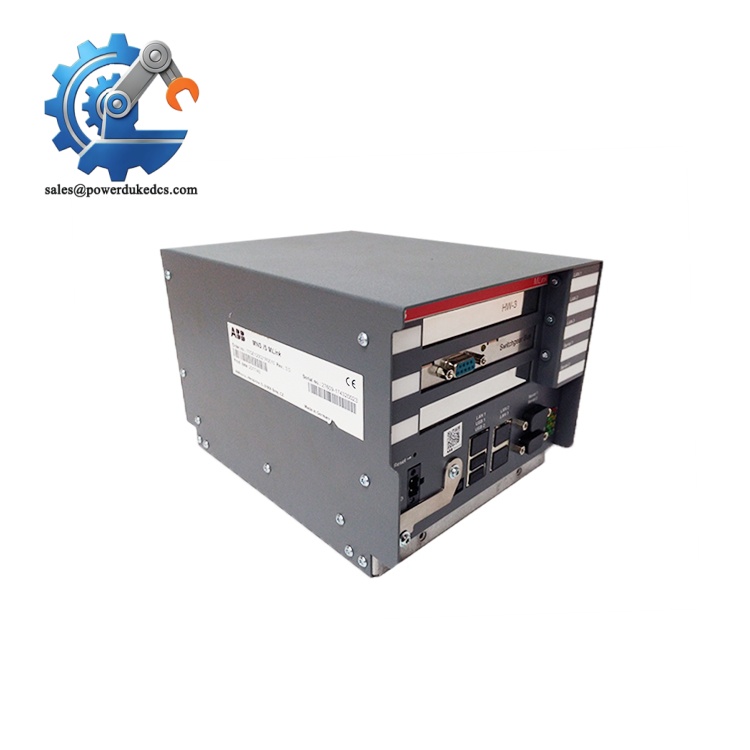
ABB 1TGE120021R0610
Quality Inspection SOP
All stocked modules undergo full-process testing to eliminate hidden quality risks for industrial MRO scenarios.
First, complete incoming inspection: verify original factory packing list and serial number traceability records. Check surface condition for no corrosion, scratches or aging discoloration. Confirm complete original accessories including factory certificate and specification documents.
Live function testing adopts ABB Relion 615 series dedicated test bench. Conduct power-on self-test to verify LED indicator logic. Perform full IEC 61850 communication handshake and GOOSE message transmission tests. Implement 24-hour continuous load operation and record real-time temperature rise data.
Electrical performance testing uses Fluke 115 multimeter and 500V megohmmeter. Ensure insulation resistance exceeds 10 MΩ with qualified ground continuity. Read and record the exact firmware version, then back up all default configuration parameters.
Final QC confirmation by professional inspectors. Seal modules with anti-static bags and bubble wrap, attach QC Pass labels with test dates. Test videos and reports can be provided upon customer request.
Field Replacement Pitfall Guide
❗ Firmware Version Mismatch Risk
Different firmware versions carry subtle differences in IEC 61850 protocol parsing. New modules with updated firmware often trigger communication timeout with old on-site IEDs. A site case showed a 2-day system debugging delay caused by unmatched firmware versions. Always record the original firmware version before replacement and confirm version consistency with suppliers in advance. Downgrade or upgrade firmware adaptively if mismatch occurs.
❗ Unreplicated Switch Configuration Risk
Default factory settings do not match on-site bus address and baud rate requirements. Most on-site errors come from neglected DIP switch replication. Take photos of the old module configuration before disassembly and compare item by item before powering on. Remember bus terminal 120Ω resistor only needs enabling at two bus endpoints.
❗ Interface Wiring Definition Deviation
Even for same-series modules, partial pin definitions may differ by batch. Do not rely on empirical wiring. Check the official wiring diagram before rewiring. Standardize shielded cable single-end grounding to avoid signal interference causing packet loss.
❗ Static Breakdown Damage
Communication module circuit boards are highly sensitive to static electricity. Dry winter environments raise breakdown risks significantly. We have seen unprotected operation cause direct module burnout and equipment replacement losses. Always use anti-static tools and operation pads during installation.
❗ Power Load Margin Insufficiency
Additional communication modules increase overall cabinet power consumption. Failure to reserve 20% power margin may lead to unstable voltage and intermittent offline communication. Calculate total load before modification and add power modules if approaching power upper limit.
Standardizing these checks saves nearly 90% of on-site debugging rework time.
Frequently Asked Questions (FAQ)
1. Is the ABB 1TGE120021R0610 fully compatible with all Relion 615 series IED devices?
It matches most mainstream 615 series feeder and transformer protection IEDs. Well, technically it requires matching firmware iterations. Individual early-version devices need minor firmware upgrades to achieve full IEC 61850 linkage. We can confirm compatibility based on your on-site device model and version.
2. Does this module support hot-swap replacement during system operation?
No. This communication expansion module does not support hot swapping. You must switch the system to maintenance state and cut off power before replacement. Live plugging will trigger communication port burnout and system program abnormality.
3. What is the actual delivery cycle and warranty policy?
We keep buffer stock for this conventional model. Goods can be shipped within 1-3 working days after order confirmation. All products come with a 12-month industrial warranty. Quality problems caused by non-human damage support free replacement and technical after-sales service.
4. Can you provide official test reports and configuration guidance?
Yes. We support provision of live test videos, parameter test reports and firmware version records. Professional engineers offer remote configuration and debugging guidance to help restore system normal operation quickly.
5. What is the difference between 1TGE120021R0610 and ordinary universal communication modules?
Three core differences: strict IEC 61850 full standard compliance, substation-grade wide temperature adaptive design, and <10 ms ultra-fast GOOSE response. Universal modules cannot meet power industry precision synchronization and high-reliability operation requirements.
6. Will replacing the module cause on-site data loss?
It will not affect historical data and program logic stored in the main IED. Only temporary communication link interruption occurs during replacement. Back up programs in advance per standard procedures to ensure zero data risk.




 Start Chat


