

Description
Product Core Brief
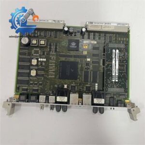
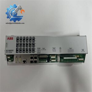
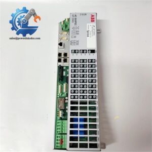
- Model: 216MB66 HESG324510M1
- Brand: ABB
- Series: AC800PEC High Performance Control Platform
- Core Function: Collect field digital signals and execute fast switching output for power electronic closed-loop control
- Type: Digital Input & Output I/O Module
- Key Specs: Optical fiber backplane link, microsecond-level signal sampling, DIN rail rack mount, EMC industrial grade
- Condition: New Original, non-refurbished
- Stock Reminder: Limited spot inventory available
Product Introduction
For power plants and metallurgical factories running high-speed rectifier and converter control systems, signal synchronization directly affects process stability. The ABB 216MB66 HESG324510M1 serves as a peripheral I/O module within the AC800PEC control system. It establishes real-time signal exchange between the main PAC controller and on-site switching devices.
Unlike conventional slow I/O modules for general PLCs, this unit uses optical communication to cut electrical interference risks along signal lines. It handles synchronous sampling required by high-speed power control loops, supporting control cycles down to hundreds of microseconds. Multiple modules can be arranged in racks to expand field signal capacity. On-site maintenance records show it matches perfectly with rectifier, DC drive and potline control applications.
Key Technical Specifications
| Parameter Item | Technical Value |
|---|---|
| Full Part Number | 216MB66 HESG324510M1 |
| Applicable Platform | ABB AC800PEC Control System |
| Module Category | Digital Input / Digital Output I/O Module |
| Backplane Communication | Optical fiber PEC link (electrical isolation) |
| Signal Processing Cycle | Microsecond level synchronous sampling |
| Mounting Standard | Standard DIN rail rack installation |
| Supply Voltage | 24 V DC (supplied via rack backplane) |
| Operating Temperature | -20 °C ~ +70 °C |
| Cooling Method | Passive natural convection, no fan required |
| EMC Rating | Industrial heavy electromagnetic interference standard |
| Typical Application | Rectifier control, aluminum potline, medium voltage drive automation |
Installation & Configuration Guide
Stage 1: Pre-Installation Preparation (10 Minutes)
⚠️ Safety Priority Notify operation staff and lock out the relevant AC800PEC control rack. Cut off rack power supply completely and wait 5 minutes for internal capacitors to discharge. Confirm all connected power electronics equipment has been safely shut down.
Tool Preparation ESD anti-static wristband, PH1 screwdriver, digital multimeter, mobile phone for photo recording, label stickers.
Backup Work Upload the complete control project from AC800PEC programming software. Take clear photos of old module wiring, fiber cable arrangement and DIP switch settings.
Stage 2: Old Module Removal (12 Minutes)
- Mark each external signal cable and optical fiber before disconnection.
- Loosen terminal screws and separate field wiring one by one.
- Unplug optical fiber connectors gently; avoid bending fiber below minimum bending radius.
- Release DIN rail lock at module bottom, pull out the I/O card vertically from rack slot.
- Inspect rack backplane connector pins for oxidation or deformation; blow away dust with dry compressed air if needed.
⚠️ Note: Do not touch fiber end surfaces with fingers, contamination will cause communication attenuation.
Stage 3: New Module Installation (15 Minutes)
- Wear anti-static wristband before unpacking ABB 216MB66 HESG324510M1. Double verify full part number.
- Insert module vertically into designated rack slot until locking buckle clicks into place.
- Replicate DIP switch configuration fully according to photos taken from the original unit.
- Reconnect optical fiber and field signal cables following labeled layout.
- Tighten terminal screws with moderate torque and pull each wire lightly to check fixation.
Self-Check List [ ] Module locked firmly on DIN rail [ ] Fiber connectors fully seated [ ] All signal wiring matches original layout [ ] No foreign debris left inside rack
Stage 4: Power-On & Functional Testing (30 Minutes)
Measure rack 24V DC supply voltage before restoring power.
- Switch on control rack power and observe module status LEDs.
- Open AC800PEC programming tool to scan rack hardware; confirm the new module is detected normally.
- Compare firmware version against the replaced module.
- Download backup control program and enter online mode.
- Trigger simulated digital input signals and verify corresponding feedback on software.
- Force digital output channels to check on-site actuator response.
- Maintain continuous running observation for minimum 30 minutes, monitor optical link status without communication loss.
- Record module serial number and replacement time in equipment maintenance logs.
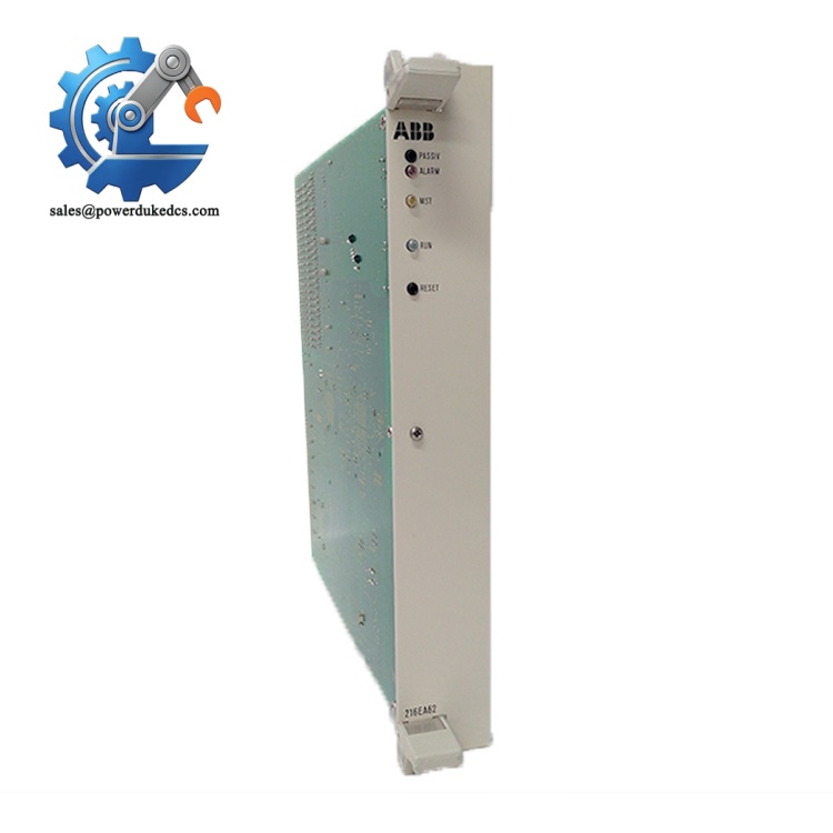
ABB 216MB66 HESG324510M1
Strict Quality Inspection Process
1. Warehouse Receiving Verification
Every incoming module undergoes serial number verification against ABB factory records. Inspect housing for scratches, deformation or disassembly traces. Check complete original accessories including packing materials and factory certificates.
2. Live Functional Testing
All units are tested on a complete AC800PEC test rack. Execute power-on self-test and LED function inspection. Establish optical fiber communication link with main controller and verify stable data transmission. Simulate digital input and output signals to validate full channel performance. Continuous 24-hour aging test monitors signal stability, and formal test reports can be provided upon request.
3. Electrical Parameter Detection
Carry out 500V insulation resistance testing, all test results above 10 MΩ. Check internal power circuit to eliminate hidden short-circuit risks. Verify isolation performance between field signals and internal control circuits.
4. Firmware & Switch Configuration Verification
Read and record factory firmware revision for each module. Document default DIP switch positions. We support firmware adjustment if customer site systems require specified versions.
5. Final QC & Packaging
Qualified modules are sealed inside anti-static bags after inspector confirmation. Wrap with bubble film and pack into reinforced cartons. Each package carries a QC Pass label printed with inspection date. Customers can apply for test photos and operation videos before shipment.
On-Site Replacement Pitfall Guide
1. Firmware Version Mismatch
Different firmware revisions can lead to optical link handshake failure. One maintenance case: engineers swapped modules directly, and the AC800PEC rack failed to recognize the I/O card for hours. Avoidance: Record firmware version of the original module before removal, confirm matching requirements before ordering spare parts.
2. Optical Fiber Improper Handling
Over-bending fiber cables or touching fiber end faces creates high signal loss, triggering intermittent communication faults. Avoidance: Keep fiber bending radius above specified limit. Use clean lens paper if fiber ends need cleaning.
3. DIP Switch Setting Deviation
Module station address and bus parameters are set via DIP switches. Wrong configuration causes rack hardware conflict. Avoidance: Take high-definition photos before removal, copy every switch position one-to-one.
4. ESD Damage
The internal signal circuit is sensitive to static electricity, especially in low-humidity workshop environments. Avoidance: Anti-static wristband is mandatory during all disassembly and installation steps. Do not expose circuit boards without protection.
5. Signal Wiring Interference
Unshielded cable routing near high-power lines causes false digital triggering. Avoidance: Separate low-voltage signal cables from power cables, follow official wiring recommendations for shielding grounding.
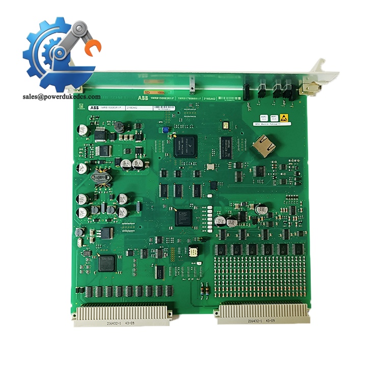
ABB 216MB66 HESG324510M1
Frequently Asked Questions (FAQ)
1. Can ABB 216MB66 HESG324510M1 be directly plug-and-play replacement? Physical installation supports direct slot insertion. Stable operation requires matching firmware version and consistent DIP switch configuration. Mismatched settings will result in communication failure.
2. What warranty is available for this I/O module? We provide 12-month warranty for new original units. Failures caused by non-human damage qualify for after-sales support. All test data is archived for quality traceability.
3. Can this module work with other ABB control series besides AC800PEC? No. It is exclusively designed for AC800PEC platform and cannot communicate with AC800M or other controller families.
4. Can I obtain inspection materials before shipment? Yes. We can supply QC photos, channel test records and short test videos for confirmation before delivery, supporting customer incoming inspection procedures.
5. Which industrial applications commonly adopt this module? Mainly aluminum electrolysis potline control, high-power rectifier systems, rolling mill drives and other facilities relying on AC800PEC high-speed power control.
6. How long is the delivery cycle for stocked modules? Limited inventory is available. Confirmed orders can be shipped within 1–2 working days. Express delivery options can shorten equipment downtime.
If you want me to condense paragraphs to adapt for 1688 product page display, let me know.



 Start Chat


