

Description
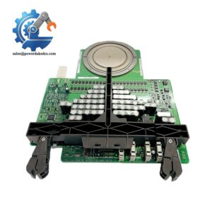
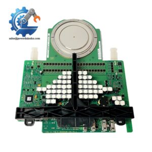
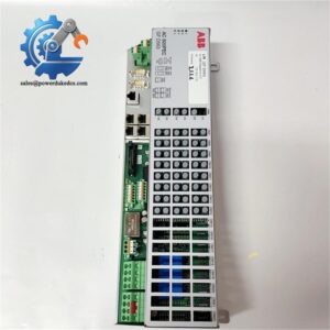
- ABB 5SHX0660F0002 | Press-pack IGCT Unit For Industrial High Power Conversion Systems
Product Core Brief
- Model: 5SHX0660F0002
- Brand: ABB
- Series: 5SHX Press-pack IGCT family
- Core Function: High-power bidirectional switching device for medium voltage power converters
- Type: Integrated Gate Commutated Thyristor (IGCT) assembly with driver PCB
- Key Specs: Press-pack package, matched built-in gate drive circuit, optimized for continuous heavy-load switching
- Condition: New Surplus, non-refurbished
⚠️ Original factory production ongoing, factory lead time is long for direct orders, limited spot inventory available
Product Introduction
Key Technical Specifications
| Parameter | Specification |
|---|---|
| Part Number | 5SHX0660F0002 |
| Device Type | Press-pack IGCT with integrated driver PCB |
| Package Form | Disc press-pack mechanical structure |
| Application Scene | Medium voltage frequency converter, high power inverter |
| Built-in Circuit | Gate drive, monitoring and auxiliary power circuit |
| Cooling Method | Water cooling or forced air cooling via heatsink |
| Mechanical Installation | Clamping mounting, requires defined clamping force |
| Operating Temperature Range | -20 °C ~ +85 °C |
| Protection Features | Overcurrent and overtemperature monitoring via driver board |
| Compatible Equipment | ABB medium voltage power conversion systems |
| Storage Condition | Dry storage, humidity below 60% without condensation |
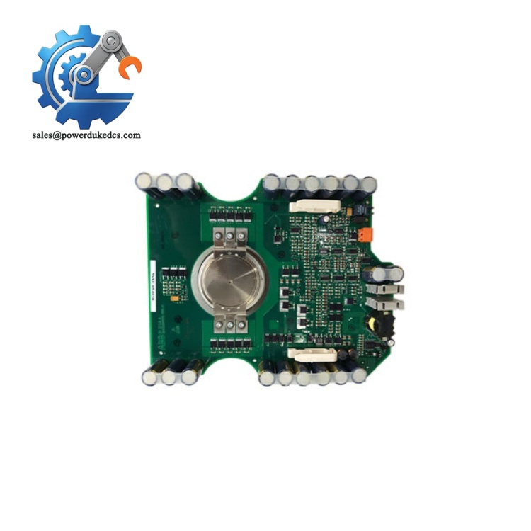
ABB 5SHX0660F0002
Installation & Configuration Guide
Pre-Installation (Estimated: 15 min)
- Coordinate maintenance window with operation department to schedule full equipment shutdown
- Lock out power supply and confirm no residual voltage inside DC bus capacitors
- Wait minimum 15 minutes for complete capacitor discharge
- Mark all power terminals and signal connectors before disassembly
- ESD wrist strap and anti-static work mat
- Torque wrench for IGCT clamping assembly
- Digital multimeter
- Digital camera for recording wiring layout
- Insulation testing megohmmeter (500 V)
- Capture full photos of original IGCT assembly, cable routing and connector positions
- Record fault logs stored in drive control unit for post-replacement comparison
Old Unit Removal (Estimated: 20 min)
- Label every signal cable and power connection terminal one by one
- Disconnect low voltage gate signal wiring first; then release main power bus connections
- Loosen heatsink clamping bolts evenly following specified torque sequence
- Take out the original 5SHX0660F0002 assembly vertically, avoid scraping PCB circuits
- Clean contact surfaces of heatsink; remove residual thermal interface material
- Inspect copper contact plates for scratches, oxidation or deformation
New Module Installation (Estimated: 25 min)
- Wear complete ESD protection, remove unit from anti-static packaging
- Verify part number marking matches required spare part
- Check driver PCB surface: no scratch, capacitor bulging or pin bending
- Place IGCT unit between upper and lower heatsink plates, keep alignment centered
- Tighten clamping bolts gradually in diagonal sequence to reach factory specified torque
- Reconnect signal cables strictly following photographed reference positions
- Complete pre-power checklist:
☑ Clamping torque meets specification
☑ All signal connectors fully locked
☑ No stray wires near high voltage bus
☑ Cooling pipeline connection secured without leakage risk
Power-On & Function Test (Estimated: 40 min)
- Measure insulation resistance between power terminals to rule out short circuit
- Confirm cooling system pump or fan runs normally before high voltage energization
- Switch on auxiliary control power only, do not close main high voltage breaker
- Check driver board status LED lights; steady green indicates normal standby state
- Upload system fault history and clear old fault records
- Apply high voltage gradually under no-load mode
- Run equipment through low-speed test cycle, monitor device temperature continuously
- Maintain 1 hour continuous no-load running, confirm no new drive alarms
- Switch to partial load for final verification before restoring full production
- Driver board alarm: Check signal wiring contact and cable shielding grounding
- Excessive temperature rise: Recheck IGCT clamping force and thermal contact surface
- Trigger failure: Confirm no damaged pins on gate signal connectors
Frequently Asked Questions (FAQ)
A: Not recommended. This assembly is factory matched. We have encountered cases where mismatched driver and IGCT lead to unreliable triggering and instant device breakdown. Use the complete integrated unit directly.
A: Absolutely not. All high voltage must be cut off and capacitors fully discharged before removal. Hot removal triggers short circuit and permanent damage to power circuit.
A: Torque parameter follows the service manual of your medium voltage converter model. Different frame sizes adopt different values. Contact us if you need to get official torque reference document.
A: Not all series versions can substitute directly. Even if appearance looks similar, internal gate drive parameters differ. Send the original equipment model number for compatibility confirmation before ordering.
A: Warranty does not cover failures caused by improper clamping force, ESD impact, overvoltage surge, wrong wiring or water condensation corrosion. All modules complete power-on testing before shipment; test records can be provided.
A: Keep inside sealed anti-static bag, place in constant temperature dry cabinet. Avoid rapid temperature change which causes condensation on PCB. Do not stack heavy objects on top of modules.
A: Common symptoms include drive reporting gate unit fault, overcurrent trip immediately after high voltage switch-on, abnormal temperature difference between power phases, visible burnt traces on driver circuit.



 Start Chat


