

Description
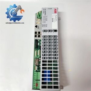
- ABB ASE2UDC920AE01 | Industrial Digital Control Module With Onboard 64MB SDRAM Memory
Product Core Brief
- Model: ASE2UDC920AE01
- ABB Material Code: 3BHB022793R0001
- Brand: ABB
- Series: ASE2UD Digital Control Series
- Core Function: Execute DeviceNet communication data exchange for high-power converter and excitation control systems
- Product Type: DeviceNet Communication & Digital Control Module
- Key Specs: Dual client/server DeviceNet operation; 64MB SDRAM, 2MB SRAM; support standard DeviceNet baud rates
- Condition: New surplus stock, factory tested
- Lifecycle Notice: ⚠️ Discontinued by ABB, limited remaining inventory
Product Introduction
Key Technical Specifications
| Parameter Item | Technical Data |
|---|---|
| Full Order Code | ASE2UDC920AE01 / 3BHB022793R0001 |
| Communication Protocol | DeviceNet |
| Operating Mode | Simultaneous Group 2 Client (Master) & Server (Slave) |
| Supported Baud Rates | 125 kbps, 250 kbps, 500 kbps |
| Memory | 64 MB SDRAM, 2 MB SRAM |
| Supported Message Types | Polling, Strobe, COS, Cyclic I/O, Explicit Messages |
| Supply Voltage | 24 V DC ±10 % |
| Operating Temperature | -20 °C ~ +55 °C |
| Storage Temperature | -40 °C ~ +85 °C |
| Mounting Method | Rack slot installation inside power control cabinet |
| Application Platform | UNITROL excitation systems, MEGADRIVE frequency converters |
| Protection Class | IP20 (cabinet installation only) |
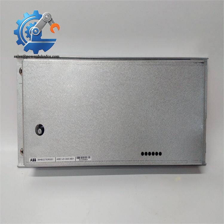
ABB ASE2UDC920AE01
Installation & Configuration Guide
Pre-Installation Preparation (12 mins)
Complete lockout-tagout procedures. Shut down main converter or excitation system. Cut all 24 V control power and high voltage supply. Maintain a minimum 10-minute wait for internal capacitors to fully discharge.
ESD wrist strap, PH1 screwdriver, digital multimeter, mobile phone for photo documentation.
Export all network configuration parameters from active control software. Capture clear photos of module cable routing, DIP switch positions and terminal wiring. Save these records for post-replacement recovery.
Old Module Removal (10 mins)
Step 2: Disconnect fieldbus cables first, then remove DC power terminals. Do not pull wires by force.
Step 3: Loosen fixing screws and pull the board straight out from the rack slot. Avoid twisting the PCB.
Step 4: Inspect backplane connectors for bent pins, oxidation or burn traces. Remove dust using dry compressed air.
New Module Installation (15 mins)
Step 2: Verify complete part number ASE2UDC920AE01 / 3BHB022793R0001. Do not install mismatched variants.
Step 3: Replicate DIP switch and terminal settings strictly following saved photos. Pay attention to DeviceNet node address and termination resistor setting.
Step 4: Insert module evenly into rack backplane and fasten mounting screws. Restore power and communication wiring in sequence.
Node address matches site requirements ✅
120 Ω termination resistor set correctly at bus endpoints ✅
All terminal connections secured ✅
No loose cables inside cabinet rack ✅
Power-On & Commissioning (25 mins)
Step 1: Restore control power and wait for module initialization sequence to finish.
Step 2: Launch system commissioning software, scan DeviceNet network and confirm the module appears on the bus.
Step 3: Import saved communication configuration and download parameter sets.
Step 4: Perform cyclic data communication test, verify signal exchange between controller and field devices.
Step 5: Run continuous no-load test for 30 minutes. Watch for bus timeout or module diagnostic alarms.
Step 6: Update equipment maintenance log with serial number and replacement date.
Quality Inspection Process
- Incoming Visual Inspection
Check part number marking, housing integrity. Confirm no traces of disassembly, scratch marks or burnt components.
- Continuity & Power-Up Test
Apply rated 24 VDC supply. Verify normal power-on LED status and no short-circuit conditions.
- Communication Function Test
Build simulated DeviceNet network to confirm master/slave switching and data transmission performance.
- Data Archiving
Record serial number, hardware revision and inspection date for full traceability.
- Final Packaging
Place qualified module into anti-static bag, pack with bubble cushion, attach QC passed label before shipment.
Field Replacement Pitfall Guide
Multiple similar ASE2UD series modules exist. ASE2UDC920AE01 cannot be substituted by other suffix versions directly. Always match the full ordering code.
Only install 120 Ω resistor at two physical ends of DeviceNet trunk. Enabling termination on middle nodes causes signal distortion and intermittent communication dropouts.
Residual voltage on backplane can damage PCB circuits during hot swapping. Power must stay disconnected long enough for capacitor discharge.
If the new module carries different firmware revision, communication handshake failures may occur. Match firmware version with original hardware whenever possible.
Memory and bus transceiver chips are sensitive to static. Skipping anti-static protection leads to invisible intermittent faults that appear months after installation.
Route DeviceNet shielded cables separately from high-power excitation wiring. Cross-interference creates unstable fieldbus signals under full load.
Frequently Asked Questions (FAQ)
-
What systems can use ASE2UDC920AE01?
It works with ABB UNITROL generator excitation platforms and MEGADRIVE medium voltage converter control racks.
-
Can this module be hot swapped?
Hot swap is not supported. All rack power must be disconnected before removal or installation.
-
Does it support both master and slave on one network?
Yes. The hardware supports simultaneous DeviceNet client and server operation to simplify hybrid network structures.
-
Where can I obtain configuration software?
You need official ABB power system commissioning tools. Generic third-party DeviceNet software only supports basic diagnostic functions.
-
Is this part still manufactured by ABB?
Production has been discontinued. All available units come from remaining new surplus inventory. Last-time-buy options are no longer open.
-
What warranty applies for stocked modules?
All units carry a 12-month warranty. Damage caused by miswiring, overvoltage surge or ESD abuse is excluded.
-
Can I change DeviceNet baud rate after installation?
Baud rate adjustment requires power cycle after parameter modification. All devices on the same trunk must use identical speed settings.



 Start Chat


