

Description
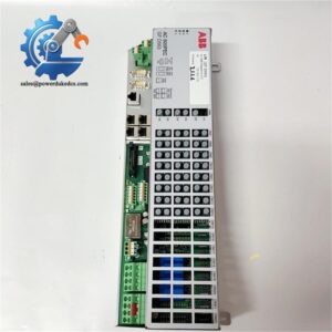
- ABB INSUMMCU2 | High-End MCU Unit With Extended Diagnostics For LV Motor Management
Product Core Brief
- Model: INSUMMCU2 (MCU2 series, variants MCU2A01C0-4 / MCU2A02V2-4)
- Brand: ABB
- Series: INSUM, MNS Modular Low Voltage Switchgear Platform
- Core Function: Execute motor control, multi-condition protection and operational monitoring for low voltage motors inside MCC drawers
- Type: Intelligent Motor Control Unit (MCU)
- Key Specs: Two current measurement ranges 0.1–3.2 A / 2.0–63 A, LonWorks fieldbus, support for star-delta and reversing starters
- Condition: New Surplus, non-refurbished ⚠️ Original production discontinued, limited available stock for retrofit
Product Introduction
Unexpected motor trips inside motor control centers can interrupt continuous process production for hours. The ABB INSUMMCU2 serves as the advanced intelligent controller built exclusively for ABB MNS switchgear INSUM architecture. It installs directly within motor starter drawers to govern start-stop logic and deliver full motor protection.
This unit upgrades the basic MCU1 platform with expanded digital I/O, voltage monitoring capability and larger fault event memory. It exchanges real-time operational data over the built-in LonWorks bus, allowing central supervision via INSUM MMI or upper-level DCS. Sites in chemical processing, water treatment and power plants have deployed this hardware for decades. One practical detail to note: matching baseplate and optional voltage measurement unit must be retained during module swap-out.
Key Technical Specifications
| Parameter Item | Technical Value |
|---|---|
| Designation | INSUMMCU2 (MCU2) |
| Supported Motor Circuits | Single-phase & three-phase AC motors |
| Current Measuring Ranges | 0.1–3.2 A; 2.0–63 A |
| Main Circuit Voltage | 380–690 V AC |
| Auxiliary Supply Options | 24 V DC / 230 V AC |
| Fieldbus Interface | LonWorks FTT-10A (78 kbps / 1.2 Mbps) |
| Digital Input Channels | 17 configurable DI |
| Contactor Control Outputs | 3 relay outputs for multi-contactor starters |
| Protection Functions | Thermal overload, phase loss, stall, earth fault, underload monitoring |
| Supported Starter Types | DOL, reversing, star-delta |
| Operating Temperature | -20 °C to +60 °C |
| Mounting Form | Drawer-mounted inside MNS MCC modules |
| Matching System | INSUM motor management system |
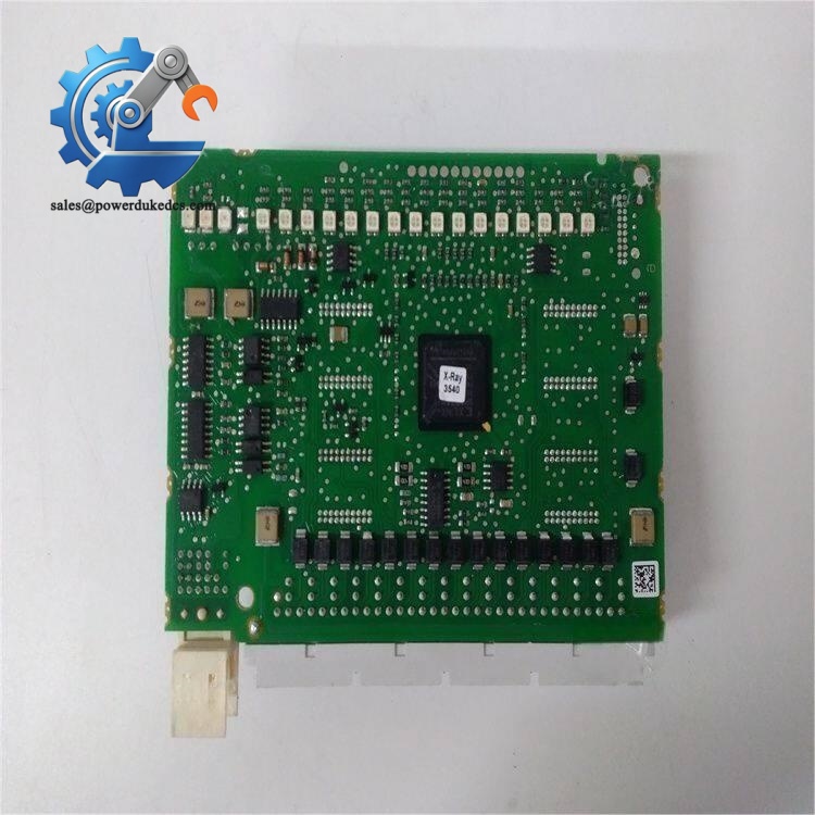
ABB INSUMMCU2
Installation & Configuration Guide
Stage 1: Pre-Installation Preparation (12 Minutes)
⚠️ Safety Priority Notify operation staff of planned MCC shutdown. Isolate the corresponding motor feeder and confirm zero energy state. Cut control power to the drawer and wait minimum 5 minutes for capacitor discharge.
Tool Preparation ESD wrist strap and anti-static mat, PH1 screwdriver, Fluke multimeter, marker tape, mobile phone for recording wiring and jumper configuration.
Backup & Recording Export all motor protection parameter settings from the existing INSUMMCU2 via WinSUM software. Photograph terminal wiring layout and module orientation inside the drawer. Save fault history logs before removal.
Stage 2: Old Module Removal (12 Minutes)
- Capture clear photos of all wiring connections before detaching any cables. Label each wire according to terminal numbers.
- Loosen terminal screws counterclockwise and detach wiring steadily. Avoid pulling cables hard to prevent terminal pin deformation.
- Release the module fixing hardware inside the MCC drawer, extract the unit vertically without twisting the ribbon communication cable.
- Inspect drawer backplane connectors and ribbon cable contacts for oxidation or bending. Clean contact surfaces with compressed air if dust accumulates.
⚠️ Note: Record all locally set protection parameters written on module housing, these values speed up post-replacement commissioning.
Stage 3: New Module Installation (18 Minutes)
- Wear ESD protection before taking INSUMMCU2 out of anti-static packaging.
- Verify full model variant matches the removed unit, confirm compatibility with existing baseplate.
- Route the internal communication ribbon cable correctly, align the module into mounting guides inside the drawer.
- Secure module mounting fasteners with moderate torque. Reconnect field wiring strictly following labeled photos.
- Double-check contactor control outputs, CT wiring and auxiliary power connections.
Self-Check List Baseplate compatibility confirmed ✅ | Ribbon cable fully seated ✅ | All wiring reconnected ✅ | Module firmly fixed inside drawer ✅
Stage 4: Power-On & Functional Testing (25 Minutes)
Perform resistance check for short circuits on auxiliary power terminals before energizing the drawer.
- Restore control power first, observe module LED indicators to confirm normal initialization.
- Launch WinSUM engineering software, scan the INSUM LonWorks network to detect the new MCU2 unit.
- Import pre-backed-up motor protection parameters and download configuration to the module.
- Execute local start-stop tests to verify contactor sequence works as intended. Simulate overload conditions to confirm protection trip action.
- Keep the motor running continuously for 30 minutes. Monitor real-time current, voltage and fault status on INSUM MMI. Write serial number and replacement date to equipment maintenance records.
⚠️ Common commissioning trap: Wrong CT wiring direction will cause incorrect thermal load calculation and premature motor trips.
Frequently Asked Questions (FAQ)
1. Can INSUMMCU2 be hot swapped when the MCC drawer remains energized? No. This device does not support hot insertion. The drawer auxiliary power must be fully disconnected before removal or installation. Hot swapping risks damaging internal circuitry and triggering unexpected motor trips on adjacent starters.
2. What is the core functional difference between INSUMMCU1 and INSUMMCU2? MCU2 carries more digital inputs, three contactor drive outputs and optional voltage measurement support. It works with reversing and star-delta starters, while MCU1 only suits basic direct-on-line equipment. Upgrade from MCU1 to MCU2 usually requires rewiring drawer terminals.
3. Does INSUMMCU2 work outside the ABB MNS INSUM switchgear system? It cannot run as a standalone motor protector. Full functionality depends on INSUM baseplate, LonWorks backplane and INSUM MMI/gateway infrastructure. It will not communicate with generic third-party MCC systems.
4. Can I adjust motor protection settings directly on the module? No. All protection thresholds, starter logic and communication parameters must be configured via WinSUM PC software or INSUM MMI panel connected to the INSUM network. Local physical switches offer limited configuration options only.
5. What warranty coverage is available for INSUMMCU2 units? We provide a 12-month warranty. Every module undergoes complete bench functional testing before shipment. Test photos and video records can be supplied upon request. Damage caused by incorrect wiring, ESD impact or overvoltage surges is excluded.
6. Is a voltage measurement unit mandatory for every INSUMMCU2 installation? Not mandatory. Voltage monitoring is an optional add-on. If your site requires under/overvoltage protection or power factor measurement, the matching voltage unit must be installed together with the MCU2 main module.
If you require, I can add the full incoming QC inspection procedure section for your product webpage.



 Start Chat


