

Description
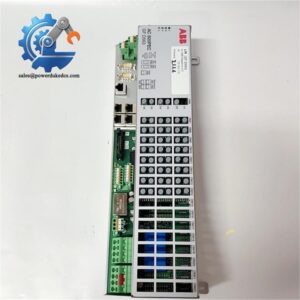
- ABB Drive Accessory NTAC-02 | On-site MRO Buffer Stock for Variable Frequency Drives
Product Core Brief
- Model: NTAC-02
- Brand: ABB
- Series: ACS600, ACS800 Drive Expansion Modules
- Core Function: Collect encoder signals and transmit feedback data to drive via DDCS optical fiber link
- Type: Pulse Encoder Interface Module
- Key Specs: Supports TTL / HTL incremental encoders, DDCS optical communication, configurable encoder supply 15V / 24V
- Condition: New Surplus, non-refurbished
Product Introduction
Key Technical Specifications
| Parameter | Specification |
|---|---|
| Model Code | NTAC-02 |
| Compatible Drives | ABB ACS600, ACS800 series inverters |
| Communication Link | DDCS fiber optic link |
| Supported Encoder Type | TTL / HTL incremental encoder (A, B, Z channels) |
| Encoder Power Output | Selectable 15 V DC or 24 V DC via internal jumpers |
| Module Supply Voltage | 24 V DC |
| Max Input Pulse Frequency | 1 MHz |
| Mounting Method | Standard 35 mm DIN rail |
| Operating Temperature | 0 °C ~ +55 °C |
| Protection Class | IP20, cabinet installation only |
| Node Address Setting | Internal DIP switches |
| Package Accessories | Fiber optic cables, mounting rail, jumper bridges |
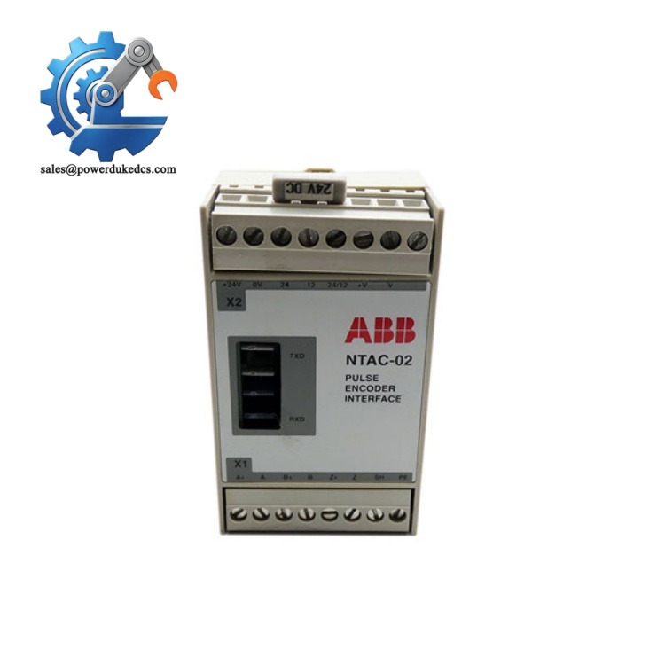
ABB NTAC-02
Quality Inspection SOP (Full Transparent Testing Process)
-
Warehouse Receiving Verification
Verify serial number traceability and original factory labels. Complete visual inspection to confirm no scratches, burnt components, or disassembly traces. Check all accessories including jumpers and fiber cables are complete.
-
Live Bench Functional Testing
Testing runs on a physical ACS800 drive test bench. Complete power-on self-test and LED status verification. Simulate encoder pulse input to validate signal receiving. Establish stable DDCS fiber communication between NTAC-02 and drive mainboard. Execute continuous 24-hour aging testing to track temperature stability.
-
Electrical Performance Testing
Use Fluke 115 multimeter to test output voltage under both 15 V and 24 V jumper settings. Perform insulation resistance test at 500 V DC. Confirm no short circuits on encoder input terminals.
-
Configuration Verification
Read and record default hardware settings. Photograph internal DIP switch positions and encoder power jumpers for customer reference. No unauthorized firmware modification will be performed.
-
Final QC & Packaging
Qualified units get anti-static sealed packaging with bubble protection. QC Passed label with test date is attached. Test photos and videos can be provided upon request before delivery.
Installation & Configuration Guide
Pre-Installation Preparation (10 mins)
Arrange equipment shutdown and lockout-tagout. Cut off 24 V control power of the drive rack. Wait at least 5 minutes for internal capacitor discharge. Back up all drive parameter sets with DriveWindow software.
Old Module Removal (12 mins)
Disconnect encoder signal terminals first, then remove DDCS fiber cables. Release DIN rail locking clip and take the module out vertically.
Check fiber connectors for dust or scratches; clean with lint-free cloth if contamination exists.
New Module Installation (15 mins)
Replicate jumper selection for encoder supply (15 V or 24 V) and DIP switch node address exactly according to photos.
Mount NTAC-02 onto DIN rail and lock firmly. Reconnect encoder wiring and DDCS fiber cables. Ensure fiber connectors click into place.
All terminals tightened; fiber installed correctly; no loose wire strands inside the module housing.
Power-On & Functional Commissioning (30 mins)
Connect DriveWindow to check if the drive recognizes the NTAC-02 over DDCS link. Open parameter group 50 and 98, configure encoder pulse count, signal type and rotation direction.
Run motor no-load test. Monitor actual motor speed feedback to confirm stable encoder signal reception. Maintain continuous operation for minimum 30 minutes without encoder loss alarms.
Update equipment maintenance logs with serial number and replacement date.
On-site Replacement Pitfall Guide (Engineer Practical Experience)
1. Incorrect Encoder Power Jumper Setting
We encountered one production line shutdown caused by this mistake; maintenance staff forgot to copy jumper settings from the old module.
Solution: Photograph jumpers before removing the original unit; double-check configuration before powering on.
2. NTAC-01 and NTAC-02 Cannot Be Interchanged
Solution: Always purchase the exact same model as the failed unit.
3. Poor DDCS Optical Fiber Connection
Solution: Avoid bending fiber below minimum radius; clean fiber tips using professional fiber cleaning tools during installation.
4. Missing ESD Protection During Handling
Solution: Wear ESD wrist strap every time when touching circuit boards inside the module.
5. Improper Encoder Cable Shield Grounding
Solution: Ground cable shield only on the NTAC-02 module side.
Frequently Asked Questions (FAQ)
A: Hot swap is not recommended. Removing the module while powered will break encoder feedback instantly, triggering drive faults and possible production interruption. Full power shutdown is advised.
A: NTAC-02 is designed only for incremental A/B/Z pulse encoders. It does not support SSI absolute encoder protocols. Select alternative hardware if absolute feedback is required.
A: Drive continuously reports Encoder Loss or Speed Measurement Fault; severe motor speed oscillation under closed-loop control; DDCS communication timeout between module and main control unit.
A: No. This module is exclusive to legacy ACS600 and ACS800 platforms. Newer drive generations adopt different feedback hardware structures. Confirm drive model before ordering.
A: It belongs to critical slow-moving spare parts for legacy drives. Maintain 1 unit buffer stock for each key production line to avoid long lead times. Negotiate consignment inventory with suppliers to reduce occupied capital.
A: Damage caused by static discharge, reversed encoder power wiring, overvoltage surge, water condensation, unauthorized disassembly, and physical damage on optical fiber ports. Every module passes bench communication testing before delivery.



 Start Chat


