

Description
- ABB REF541KB115AAAA Protection Relay Supports IEC 60870-5-103, SPA and LON Communication
Product Core Brief
- Model: REF541KB115AAAA
- Brand: ABB
- Series: REF 541 Feeder Terminal Series
- Core Function: Provides full protection, control, measurement and supervision for medium voltage feeders
- Type: Bay Protection Relay / Feeder Intelligent Terminal
- Key Specs: Built-in disturbance recorder, programmable logic, multi-protocol communication, graphic HMI
- Condition: New Surplus, factory intact, non-refurbished
⚠️ Discontinued legacy protection relay, limited buffer stock for substation MRO replacement
Product Introduction
Key Technical Specifications
| Parameter Item | Technical Specification |
|---|---|
| Model Number | REF541KB115AAAA |
| Product Category | MV Feeder Protection & Control Terminal |
| Main Protection Functions | Directional/non-directional overcurrent, earth fault, over/under voltage, thermal overload, CBFP, auto-reclosing |
| Measurement Functions | Current, voltage, power, energy, frequency, THD power quality monitoring |
| Communication Protocols | SPA bus, LON, IEC 60870-5-103, Modbus, DNP3.0 (IEC61850 via external adapter) |
| Data Recording | Disturbance recorder, event fault logger, fault locator |
| Configuration Tool | CAP505 Relay Configuration Software |
| Operating Temperature | -20 °C to +55 °C |
| Mounting Form | Standard panel mounting for switchgear cubicles |
| HMI | Built-in graphic display with configurable mimic diagram and LED indicators |
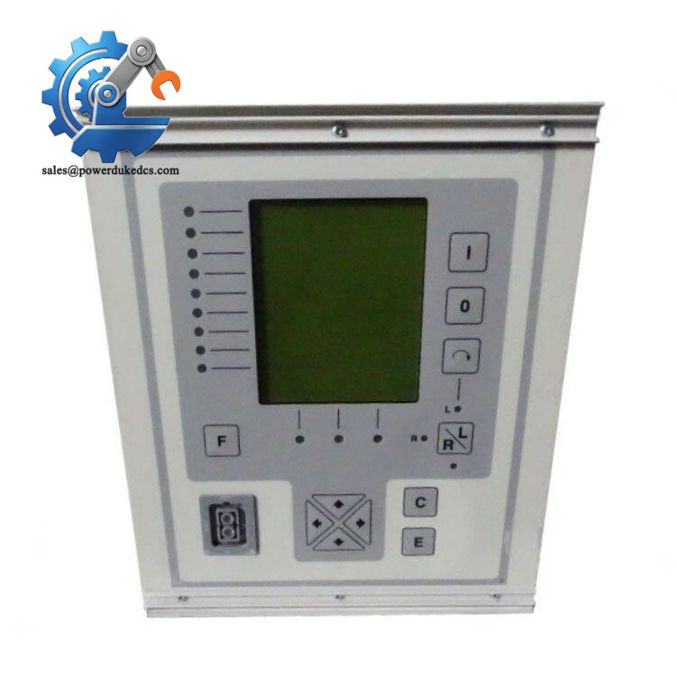
ABB REF541KB115AAAA
Installation & Configuration Guide
Stage 1: Pre-Installation Preparation (15 Minutes)
Coordinate with substation operators for scheduled outage. Isolate the target bay and confirm safety earthing applied. Disconnect auxiliary power supply and wait 10 minutes for internal capacitance discharge.
Stage 2: Old Unit Removal (10 Minutes)
Release the panel mounting fixing bolts and pull the relay outward. Inspect rear connector pins for oxidation, bending or carbon traces. Clean dust inside the wiring compartment with dry compressed air. Retain original setting records for reference.
Stage 3: New Unit Installation (18 Minutes)
Mount the relay on panel and fasten mounting bolts with uniform torque. Restore all wiring strictly following labeled terminals. Check CT circuit continuity to prevent open-circuit risk on current transformers.
Import backup parameter settings via CAP505 software, verify protection thresholds, communication addresses and logic interlock configurations. Complete self-inspection to confirm no loose terminals or residual tools.
Stage 4: Power-On & Commissioning (25 Minutes)
Switch on DC auxiliary power. Observe front panel LED status and complete self-test. Connect configuration software to verify successful online connection.
Perform secondary injection test to validate protection tripping characteristics. Test local/remote circuit breaker open/close commands and check alarm signal forwarding to SCADA. Run continuous monitoring for over 60 minutes without abnormal IRF faults. Record serial number and replacement information in substation maintenance logs.
Standard Quality Inspection SOP
Complete source traceability inspection first, verify serial number authenticity and factory documents. Visual inspection confirms housing without scratches, corrosion or repair traces.
Qualified units receive inspector confirmation, sealed with anti-static shielding and attached QC Pass labels. Test reports and operation records can be provided upon customer request.
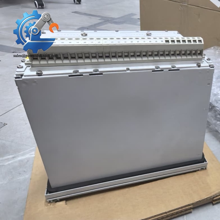
ABB REF541KB115AAAA
Field Replacement Pitfall Guide
Different firmware revisions of REF541 have subtle differences in protection logic. Directly downloading old setting files without verification may cause incorrect tripping or failure to operate. Always recheck all protection thresholds after replacement.
Never energize the CT circuit while the wiring is disconnected. Open CT secondary will generate dangerous high voltage and threaten equipment and personnel safety. Finish all wiring before power restoration.
New relays come with default factory SPA/LON addresses. Failure to modify addresses before commissioning triggers network conflict and loss of SCADA communication. Copy address settings from the original unit strictly.
The measurement and communication boards are sensitive to electrostatic discharge. Dry substation environments increase failure risk. ESD protection must be used during all disassembly and wiring work.
The mimic picture displayed on the front HMI is stored separately from protection settings. Simply importing parameter files cannot restore the mimic layout. Back up mimic configuration files separately before replacement.
Frequently Asked Questions (FAQ)
Hardware dimensions and terminals are consistent across REF541 series, but ordering suffix defines I/O allocation and firmware function sets. Cross replacement is only allowed after confirming suffix matching and re-commissioning all settings.
Hot swapping is not supported. The CT/VT secondary circuits cannot be live disconnected. The whole bay needs to be isolated and de-energized before replacement work.
We hold limited buffer stock for power station emergency maintenance. Goods can be shipped within 1–3 working days. All units carry a 12-month industrial warranty and full remote commissioning support.
Common symptoms include persistent IRF internal fault alarm, failure to record disturbance data, unstable communication dropout, incorrect protection operation and blank HMI display after power-on.
Yes. Pre-shipment test records and firmware version screenshots are supplied. Our technical team offers remote guidance for setting import, secondary injection test and SCADA communication debugging.
Historical fault and disturbance data are stored locally inside the old unit. The new relay starts with empty logs. Export all fault records from the original device before removal for archive purposes.



 Start Chat


