

Description
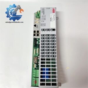
- ABB SPAU140C Relay | Panel Mount Synchro Protection Device with SPA Bus Communication
Product Core Brief
- Model: SPAU140C
- Brand: ABB
- Series: SPA series numerical protection relays
- Core Function: Validate synchronism conditions to enable safe circuit breaker closing
- Type: Synchro-Check Relay
- Key Specs: Dual independent operation stages, synchro-check & voltage-check modes, SPA optical serial bus
- Condition: New Surplus, non-refurbished
⚠️ Discontinued by ABB since 2012, factory serial production stopped, limited spot inventory available
Product Introduction
Key Technical Specifications
| Parameter | Specification |
|---|---|
| Part Number | SPAU140C |
| Device Type | Microprocessor-based synchro-check relay |
| Rated Measuring Voltage | 100 V / 110 V (VT secondary) |
| Frequency Range | 45 … 65 Hz (supports 50 Hz / 60 Hz) |
| Auxiliary Supply Range | 80 … 265 V AC / 18 … 265 V DC |
| Operating Stages | 2 independent identical stages |
| Working Modes | Synchro-check, voltage-check; continuous / command operation |
| Communication Interface | SPA serial bus (electrical or fiber optic) |
| Output Contact Rating | 250 V AC/DC, continuous 5 A |
| Mounting Form | Panel flush mounting, 4U standard case |
| Self-Supervision | Built-in hardware & software diagnostic with IRF alarm output |
| Operating Temperature | -5 °C ~ +55 °C |
| Origin | Finland |
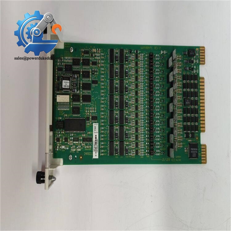
ABB SPAU140C Relay
Installation & Configuration Guide
Pre-Installation (Estimated: 12 min)
- Schedule maintenance shutdown and implement lockout-tagout procedures
- Confirm all connected voltage transformers are isolated
- Discharge residual voltage on secondary wiring of VT circuits
- Prepare documentation for original setting parameters
- ESD wrist strap and anti-static mat
- PH1 cross screwdriver
- Digital multimeter
- Camera for recording wiring layout and front panel settings
- Printed wiring diagram of the switchgear control circuit
- Record all configured threshold values: ΔU, Δf, phase angle limit
- Capture clear photos of all terminal wiring
- Save historical fault records stored inside the relay memory
Old Unit Removal (Estimated: 15 min)
- Label every VT signal wire, auxiliary power cable and relay output contact wire
- Disconnect low-current measurement circuits first; avoid open-circuit risk on VT secondary loops
- Remove front panel cover, then unscrew mounting fasteners around the relay housing
- Pull the relay slowly outward from the cutout panel
- Inspect terminal blocks for oxidation, overheating marks or loose screw traces
New Module Installation (Estimated: 18 min)
- Apply ESD protection before unpacking the relay
- Match model designation and auxiliary voltage version with the removed unit
- Fit the relay into the panel cutout and secure mounting screws evenly
- Reconnect wiring strictly following photographed reference layout
- Access setting menu and restore all synchronism parameters from backup records
- Complete pre-power checklist:
☑ All VT circuits wired without reversed polarity
☑ Auxiliary power terminals correctly connected
☑ No exposed loose conductors inside cabinet
☑ Communication cable matched for electrical or optical SPA bus
Power-On & Function Test (Estimated: 35 min)
- Measure auxiliary supply voltage to stay within 80–265 V range
- Verify no short circuits exist on voltage measurement inputs
- Switch on auxiliary power only; keep all primary high voltage circuits isolated
- Check front panel display, confirm no permanent IRF fault codes
- Navigate menu to verify all restored setting values
- Inject simulated voltage signals via secondary injection test set
- Test both synchro-check and voltage-check logic for Stage 1 and Stage 2
- Confirm output contacts actuate only when all synchronism thresholds are satisfied
- Run continuous monitoring test for minimum 30 minutes, record operation status
- IRF fault code displayed: Internal hardware defect, replacement required
- No closing permission output: Check phase sequence, VT polarity or threshold limits
- SPA bus communication failure: Inspect fiber cable or terminal termination resistance
Frequently Asked Questions (FAQ)
A: Direct plug-and-play swap is not available. Newer generation devices use different terminal definitions and logic architectures. Modifications to control wiring and logic interlocks will be required.
A: Hot removal is not recommended. Interruption of VT secondary wiring during live maintenance creates dangerous high voltage risks on open terminals. Full auxiliary power shutdown is mandatory.
A: Continuous mode delivers permanent closing permission once conditions are met, often used for automatic bus transfer schemes. Command mode only triggers output after receiving external closing request signals, widely adopted for manual breaker control panels.
A: Yes. The dual independent stages allow monitoring two breakers simultaneously. Each stage can be configured separately for synchro or voltage check logic. We have implemented this layout on multiple duplex substation projects.
A: Setting values are saved in non-volatile memory. Short power cuts do not erase configurations. Extended storage without power does not affect saved parameters.
A: Phase angle measurement generates wrong readings. The relay will continuously reject closing commands even under actual synchronized conditions. Verify phase sequence before commissioning.
A: Warranty excludes failures induced by incorrect wiring, transient overvoltage, lightning surges or improper secondary injection testing. All units complete bench testing before dispatch, test records can be provided upon request.



 Start Chat


