

Description
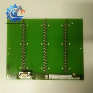
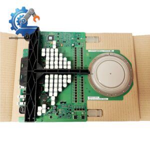
- ABB 3BHB007211R117 Circuit Board | On-board Signal Filtering & Galvanic Signal Transfer Unit
Product Core Brief
- Model: XVC768117
- Full Part Code: 3BHB007211R117
- Brand: ABB
- Series: XVC sub-print circuit board series
- Core Function: Process and transfer low-level feedback signals inside medium voltage power converters
- Type: Rack-mounted interface printed circuit board
- Key Specs: On-board signal filtering, galvanic signal isolation, edge connector interface
- Condition: New Surplus, non-refurbished
⚠️ Original factory series has entered phase-out status, factory lead time extends significantly, spot inventory limited
Product Introduction
Key Technical Specifications
| Parameter | Specification |
|---|---|
| Design Part No. | XVC768117 |
| Order Code | 3BHB007211R117 |
| Product Form | Printed Circuit Subboard (Subprint) |
| Core Function | Analog signal conditioning, noise filtering, signal transfer |
| Interface Type | Multi-pin edge connector for rack backplane connection |
| Signal Isolation | On-board isolation components for measurement circuits |
| Working Supply | Low voltage auxiliary supply inside converter rack |
| Operating Temperature | 0 °C ~ +60 °C |
| Storage Temperature | -40 °C ~ +70 °C |
| Applicable Environment | Indoor converter cabinet, non-condensing atmosphere |
| Compatible Equipment | ABB medium voltage power conversion systems |
| Protection Coating | Conformal coating for anti-humidity and anti-dust performance |
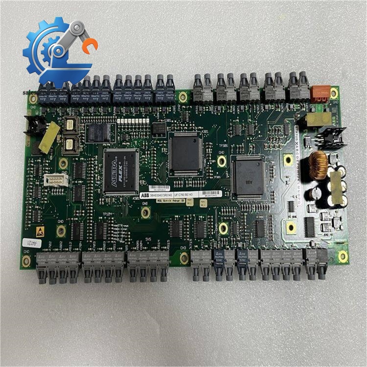
ABB 3BHB007211R117
Installation & Configuration Guide
Pre-Installation (Estimated: 15 min)
- Arrange formal equipment shutdown and lockout-tagout procedures
- Cut off all high voltage and auxiliary control power
- Hold minimum 20 minutes to fully discharge DC bus capacitors
- Prepare cabinet wiring diagram and spare connector accessories
- ESD wrist strap and anti-static work mat
- PH0 cross screwdriver
- Digital multimeter
- Mobile camera to record slot layout and cable routing
- Photograph original board position and all plugged wiring
- Record existing fault history stored in the converter controller
- Check for signs of overheating on adjacent circuit boards
Old Unit Removal (Estimated: 18 min)
- Mark all loose signal harnesses connected to the subboard
- Carefully unplug front side signal cables one by one
- Release fixing screws securing the board inside the rack slot
- Pull the board horizontally outward, avoid bending edge connector pins
- Inspect rack backplane contacts for oxidation or burn marks
New Module Installation (Estimated: 20 min)
- Wear complete ESD protection before unpacking the circuit board
- Verify full part number XVC768117 / 3BHB007211R117 matches required spare
- Check conformal coating, PCB traces and connector pins for transport damage
- Slide the new board smoothly into the designated rack slot
- Tighten fixing screws evenly to secure the subboard
- Reconnect signal cables strictly according to photographed layout
- Complete pre-power checklist:
☑ Edge connector fully engaged with rack backplane
☑ All signal cables firmly locked
☑ No loose wiring inside the rack compartment
☑ No metal debris left near circuit components
Power-On & Function Test (Estimated: 40 min)
- Confirm auxiliary power wiring polarity is correct
- Check no short-circuit paths on signal terminals
- Switch on auxiliary control power only; keep main high voltage disconnected
- Access converter diagnostic menu, confirm no new hardware fault codes
- Read real-time measurement signals and verify stable signal readings
- Execute no-load startup sequence for the power converter
- Monitor signal values continuously for minimum 1 hour
- Simulate load changes to confirm feedback signals respond smoothly
- Constant signal drift: Inspect edge connector cleanliness and seating status
- Hardware fault alarm: Confirm matching hardware revision between subboard and main controller
- No measurement signal output: Check broken wiring or reversed harness pin assignment
Frequently Asked Questions (FAQ)
A: Direct interchange is not supported. Even visually identical XVC boards carry different internal component layouts and signal routing. Mismatched versions result in measurement deviation and protection trips. Send full converter model number to confirm compatibility before ordering.
A: Hot swap is strictly forbidden. Live removal damages edge connectors and may induce voltage spikes that destroy adjacent control hardware. Full power shutdown and capacitor discharge are mandatory.
A: Common symptoms include fluctuating current/voltage feedback values, intermittent converter trip without clear root cause, constant measurement offset, or communication loss between sensor circuits and main CPU.
A: Control parameters store inside the main controller instead of this interface board. No parameter re-download is required, but signal calibration might be necessary after replacement.
A: Small coating scratches are acceptable if PCB copper traces remain intact. Large peeling or crack areas increase risk of short circuit under humid operating conditions.
A: Seal inside original anti-static bag, store in dry constant-temperature cabinet. Avoid temperature fluctuation that creates condensation on PCB surfaces. Do not stack heavy items on circuit boards.
A: Warranty does not cover damage caused by ESD shock, wrong wiring, overvoltage surges, liquid ingress, improper installation torque, or physical bending of PCB. Every unit undergoes bench signal testing before delivery; test records are available on request.



 Start Chat


