

Description
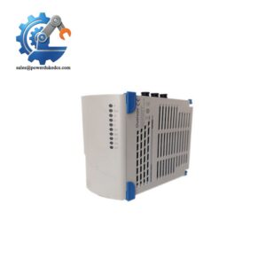
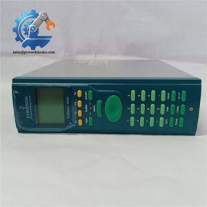
- Emerson P144.R4 | Field Signal Interface Module for Petrochemical & Power Plant Control
Product Core Brief
- Model: P144.R4
- Brand: Emerson
- Series: Legacy Rack-based Process Control I/O Series
- Core Function: Process mixed analog and digital field signals for distributed control systems
- Type: Rack-mounted I/O interface circuit board
- Key Specs: Supports multi-channel AI/DI signal conditioning, rack backplane bus communication, 24 V DC operation
- Condition: New Surplus, fully bench tested before delivery ⚠️ OEM production discontinued, limited available inventory
Product Introduction
Unexpected I/O board failure can cut off communication between field transmitters and the central control system. The P144.R4 serves as the intermediate signal processing unit inside Emerson legacy control racks. It collects raw field signals, performs filtering and level conversion, then transmits standardized data to the main controller via rack backplane.
This revision R4 hardware fixes minor signal drift issues found in earlier P144 variants. It handles both low-level analog measurement signals and dry contact digital inputs simultaneously. Long-term site feedback proves stable operation under high electromagnetic interference environments, widely deployed in power generation, chemical processing and pipeline monitoring facilities.
Key Technical Specifications
| Parameter | Details |
|---|---|
| Full Part Number | P144.R4 |
| Supply Voltage | 24 V DC (Range: 20 V DC ~ 32 V DC) |
| Signal Type Support | Analog Input, Digital Dry Contact Input |
| Communication | Internal rack backplane parallel bus |
| Operating Temperature | -20 °C ~ +65 °C |
| Storage Temperature | -40 °C ~ +85 °C |
| Relative Humidity | 5% ~ 95 %, non-condensing |
| Mounting Form | Standard plug-in rack card |
| Protection | On-board surge suppression for field terminals |
| Typical Application | Process plant DCS control rack, continuous production monitoring |
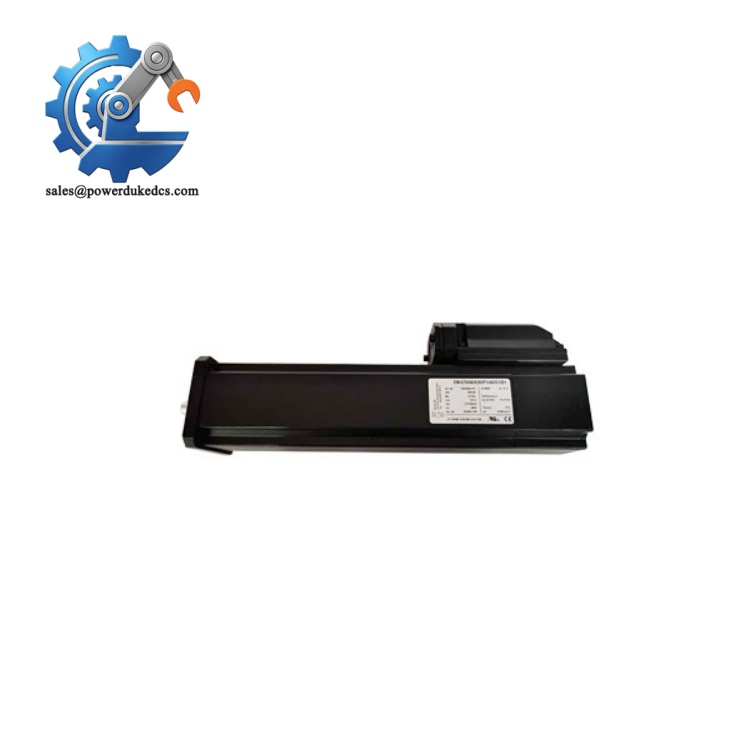
Emerson P144.R4
Installation & Configuration Guide
Phase 1: Pre-Installation (Estimated 10 minutes)
⚠️ Safety Reminders:
- Confirm planned maintenance window with operation team. Lock relevant control loops if necessary.
- Shut down the control rack power supply completely. Wait minimum 5 minutes for internal capacitors to discharge.
- ESD protection is mandatory during all handling of this PCB module.
Tools you need:
- Anti-static wrist strap + anti-static mat
- PH1 screwdriver
- Digital multimeter
- Mobile phone for photo recording of wiring and slot layout
Backup work:
- Capture photos of original module wiring and slot location.
- Record existing system configuration parameters for later verification.
Phase 2: Remove Original Module (Estimated 12 minutes)
- Disconnect all field wiring terminals connected to the front edge connector. Label each wire clearly.
- Loosen the two captive screws on the module front panel.
- Pull the board straight out horizontally. Do not twist the card to avoid bending backplane gold contacts.
- Inspect rack backplane connector. Blow dust away with dry compressed air. Do not touch contact pins directly.
Note: Keep all wiring labels intact to avoid connection errors during reinstallation.
Phase 3: Install New P144.R4 (Estimated 10 minutes)
- Wear anti-static wrist strap before opening anti-static packaging.
- Verify full part number: P144.R4. Earlier hardware revisions cannot replace R4 directly without parameter adjustment.
- Align the circuit board with the target rack slot, push steadily until fully engaged with backplane.
- Tighten front panel captive screws evenly; avoid over-tightening.
- Reconnect field wiring following photographed reference.
Pre-power checklist: [ ] Module fully locked into designated rack slot [ ] No bent pins on backplane connector [ ] All field cables correctly terminated [ ] No metal scraps left inside the rack enclosure
Phase 4: Power-On & Function Test (Estimated 20 minutes)
Pre-power inspection: Check field wiring for short circuits before energizing the rack.
Power-up sequence:
- Energize control rack power supply.
- Wait for the system controller to complete boot sequence.
- Open configuration software, confirm the control rack detects the new P144.R4 module.
- Read raw signal values from each channel, compare with actual field instrument readings.
- Trigger digital input contact status changes and verify real-time status update on HMI.
- Maintain continuous running over 30 minutes, monitor signal stability without random fluctuation.
Troubleshooting hints:
- Module not detected → Inspect backplane contact cleanliness and slot seating
- Analog signal drifting → Check field cable shielding and grounding arrangement
- Digital input no response → Verify dry contact wiring and on-board jumper settings
Frequently Asked Questions (FAQ)
- Can I hot swap P144.R4 while the control rack stays powered? Hot swap is not supported. Live removal may damage the backplane bus and trigger unexpected control action. Perform replacement during planned shutdown.
- Can P144.R4 replace older P144.R1/R2/R3 versions directly? Physical dimensions and pinout match, but minor internal circuit differences exist. After replacement, download saved configuration and validate all channel signals carefully. Some sites need small calibration adjustments.
- Will module replacement cause control loop bump or production disturbance? If the loop stays in automatic mode during power-down, process fluctuation may occur. Best practice is to switch related loops to manual state before maintenance.
- What causes unstable analog readings from P144.R4 channels? Improper single-point grounding, unshielded field cables, or proximity to variable frequency drive power wiring are the most common causes. Separate signal cables from power cables in cable trays.
- Does this module support 4-20mA HART transmitters? It supports standard 4-20mA analog signals. HART multi-drop communication is not natively enabled on this hardware. Confirm field device protocol before commissioning.
- Is P144.R4 compatible with all Emerson legacy control rack frames? It fits standard rack slots. Early rack hardware with modified backplane wiring may have compatibility risks. Cross-check rack model information before ordering.
- What warranty coverage do you provide for this spare I/O board? We provide 12-month warranty after shipment. Every unit undergoes full channel bench testing. Test photos or operation logs can be provided on request.



 Start Chat


