

Description
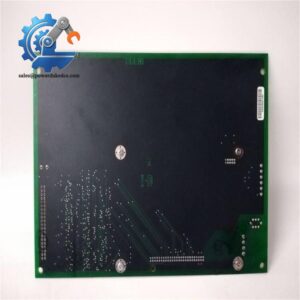
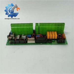
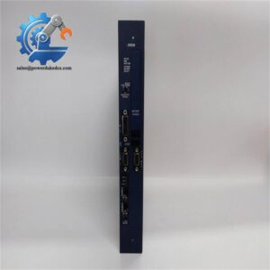
- GE DS200PCCAG1ACB | Genuine PCCA Board for Gas & Steam Turbine Excitation Control
Product Core Brief
- Model: DS200PCCAG1ACB
- Brand: General Electric (GE)
- Series: Mark V Speedtronic Turbine Control System, DS200 Hardware Family
- Core Function: PCCA Power Connect Card, transmits SCR gate drive pulses between control logic and power bridge
- Type: Gate Drive Interface Printed Circuit Board
- Key Specs: Integrated pulse transformers | Configurable hardware jumpers | Conformal coated PCB
- Condition: New Surplus, non-refurbished
⚠️ GE original manufacturing discontinued, available inventory limited
Key Technical Specifications
| Parameter | Specification |
|---|---|
| Part Number | DS200PCCAG1ACB |
| Common Name | PCCA (Power Connect Card Assembly) |
| Target System | GE Mark V Speedtronic Turbine Control / EX2000 Excitation System |
| Core Function | Isolate and transmit firing pulses to SCR power bridge |
| Configuration Method | 4 onboard configurable jumpers for signal routing adjustment |
| Circuit Component | Built-in pulse transformers for gate signal isolation |
| PCB Protection | Conformal coating against dust, humidity and mild corrosive atmosphere |
| Operating Temperature | 0 °C ~ +60 °C |
| Storage Temperature | -40 °C ~ +85 °C |
| Ambient Humidity | 5%–95%, non-condensing |
| Installation Method | Plug-in structure for standard Mark V rack |
| Approximate Net Weight | 0.68 kg |
| Certification | CE, UL certified for power generation applications |
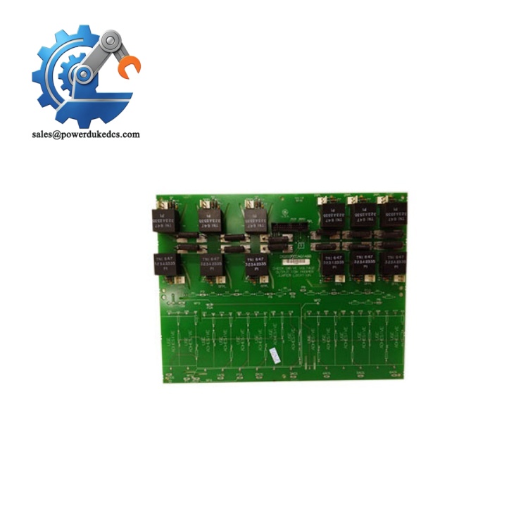
GE DS200PCCAG1ACB
Product Introduction
Application Scenarios & Pain Points
- Thermal Power Plants – Generator EX2000 Excitation Control Cabinets
SCR bridge firing control for synchronous generator excitation systems, stabilize generator terminal voltage.
- Combined Cycle Power Plants – Gas Turbine Auxiliary Drive Control
Drive and excitation regulation for gas turbine startup motors and auxiliary equipment.
- Petrochemical Industry – Large Turbine-driven Compressors
Speed control excitation circuit for process centrifugal compressors.
- Waste-to-Energy Power Plants – Steam Turbine Generator Sets
Excitation pulse control for medium and small capacity turbine generators.
- Offshore Power Generation – Islanded Turbine Generation Units
Continuous excitation control under high humidity and salt spray environment.
A 220MW thermal power plant detected excitation fluctuation during peak load operation. Troubleshooting confirmed aging components on DS200PCCAG1ACB board. GE official delivery cycle reached 52 working days. Without spare card, the generator could only operate under limited load.
The maintenance team purchased spare DS200PCCAG1ACB from available stock. Technicians recorded original jumper settings, completed board replacement and excitation loop testing within 2.5 hours. Generator voltage returned stable. The power plant added one identical board to critical MRO spare inventory afterwards.
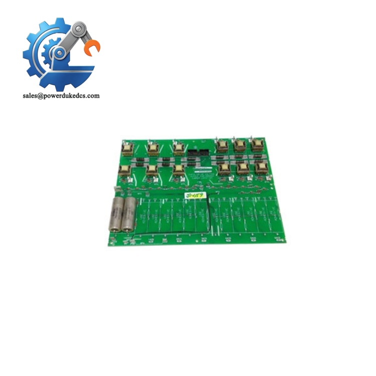
GE DS200PCCAG1ACB
Compatibility & Replacement Matrix
DS200PCCAG1ACB → DS200PCCAG5ACB / DS200PCCAG7A : Not directly interchangeable, different pulse transformer circuits for different SCR frame models
Notice: The suffix letters represent functional revision and artwork version. Do not replace without confirming site excitation cabinet hardware model.
Quality Control Process
- Incoming Inspection
Check serial number and original packaging records. Visual inspection to confirm no PCB corrosion, component burnout, scratch or disassembly traces.
- Live Bench Test
Test Platform: Standard GE Mark V rack with simulation excitation circuit
- Power-on inspection and backplane communication test
- Pulse transformer signal transmission verification
- 24-hour continuous burn-in stability test
A formal test report will be generated; test photos or videos can be provided upon customer request.
- Electrical Performance Test
500V DC insulation resistance test, insulation value ≥10 MΩ. Continuity check for all pulse channels.
- Hardware Information Recording
Record board serial number and revision label information.
- Final QC & Packaging
Attach QC Pass label. Board sealed inside anti-static bag, protected by shockproof bubble film and export carton.
Technical Pitfall Guide for On-site Replacement
Problem: Jumpers not restored to original positions after replacement, leading to disordered SCR firing sequence and excitation failure.
Tip: Take clear photos of all onboard jumpers before removing the faulty board. Copy settings completely on new card.
Real case: One power station omitted jumper recording. After replacement, excitation system threw continuous fault alarms; engineers spent more than one day adjusting jumpers.
Problem: Pulling ribbon cable violently damages internal wiring, causing intermittent pulse signal loss.
Tip: Hold the plastic connector housing instead of cables during disassembly.
Problem: Static electricity damages pulse transformers and small signal chips during maintenance.
Tip: Wear certified anti-static wristband and operate on anti-static mat.
Problem: Hard contact scrapes PCB protective coating, accelerating corrosion in humid cabinet environment.
Tip: Avoid sharp tools contacting board surface during installation.
Problem: Dust and oxidation cause unstable signal transmission after board insertion.
Tip: Clean rack slot contacts gently before installing new circuit board.



 Start Chat


