

Description
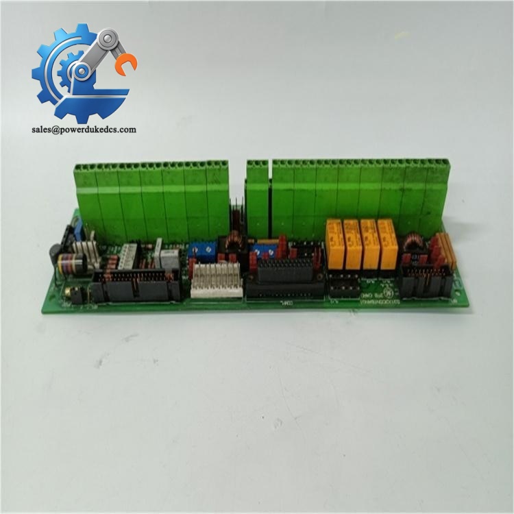
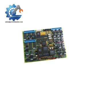
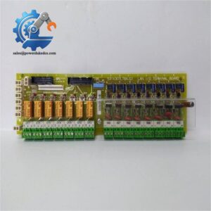
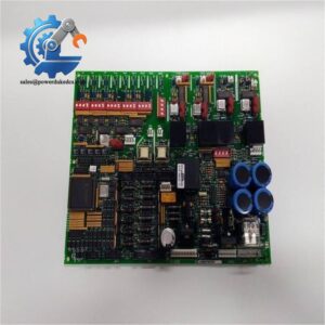
- GE 531X305NTBAJG1 | Genuine 531X Series Terminal Board, Limited Inventory Available
Product Core Brief
- Model: 531X305NTBAJG1
- Brand: GE General Electric
- Series: 531X Series Drive & Exciter Control Boards
- Core Function: NTB/3TB terminal board, signal interface between main control card and field sensors, encoders and external actuators
- Type: Drive System Terminal Interface Board
- Key Specs: 7 built-in relays | Configurable 5V/15V encoder interface | RS232C / RS422 communication
- Condition: New Surplus, non-refurbished⚠️ This legacy component is officially discontinued by GE, stock quantity limited. Alternate part reference: F31X305NTBAJG1
Key Technical Specifications
| Parameter | Specification |
|---|---|
| Full Part Number | 531X305NTBAJG1 (J Revision) |
| Product Name | NTB/3TB Drive Terminal Board |
| Compatible System | GE DC300 Drives, Mark V Turbine Control & Excitation Systems |
| Onboard Relays | 7 relays, Form A / Form C, 120 VAC contact rating |
| Encoder Interface | Jumper configurable for 5 VDC or 15 VDC encoders |
| Communication Ports | RS-232C, RS-422 serial interfaces |
| Onboard Power Output | Regulated 5 VDC, 15 VDC; Unregulated 24 VDC, 120 VAC |
| Analog Adjustment | 4 potentiometers for low-level analog I/O scaling & tach signal trimming |
| Signal Types | Digital control inputs, low-level analog feedback, speed reference signals |
| Operating Temperature | 0 ℃ ~ +55 ℃ (cabinet installation, non-condensing) |
| Installation Method | Cabinet standoff mounting, ribbon cable connection to main control board |
| Reference Manual | GEI-100020B |
Product Introduction
GE 531X305NTBAJG1 is an NTB/3TB terminal board designed for GE DC300 drives and Mark V excitation control systems. It acts as the physical signal bridge between the main drive control processor and all field devices, collecting encoder feedback, analog speed signals and discrete control commands.
This board integrates signal terminals, relay outputs, serial communication interfaces and auxiliary power distribution. Onboard potentiometers support on-site analog signal scaling without extra signal conditioners. For legacy power plant drive and excitation cabinets, it is an essential spare part; replacing a faulty terminal board avoids full system reconstruction during maintenance downtime.
Application Scenarios & Pain Points
Power plants and heavy industry facilities still operate large numbers of GE DC300 drives and Mark V excitation control systems. When this terminal board fails, operators encounter missing speed feedback, loss of relay control outputs or unstable serial communication. The drive or excitation system cannot run automatically, forcing operators into manual operation and bringing unit trip risks.
Typical Application Scenarios:
- Thermal Power Plants – Generator Excitation Control CabinetsProcess analog field current feedback and speed signals for generator excitation regulation; relay outputs execute protection and switching logic.
- Metallurgy Industry – DC Main Drive SystemsControl large rolling mill DC motors; receive encoder speed feedback and transmit analog reference signals.
- Oil & Gas – Turbomachinery Auxiliary DrivesSupport Mark V turbine auxiliary drive control, stable signal transmission for long-term continuous operation.
- Pulp & Paper – High Power DC Production Line DrivesHandle precise speed closed-loop control under continuous heavy load conditions.
- Mining – Large Conveyor DC Drive ControlDiscrete interlock signal routing and analog speed feedback collection.
Case Reference:A thermal power plant’s generator excitation system reported intermittent loss of speed feedback. Troubleshooting traced the fault to aging circuits on the original 531X305NTBAJG1 terminal board.The unit could not sustain long-term unstable excitation operation. Maintenance teams installed the replacement board during planned shutdown. After restoring jumper configuration and analog potentiometer calibration, all speed feedback and relay control functions returned normal. The plant added two spare boards to the MRO inventory for emergency maintenance.
Compatibility & Replacement Matrix
531X305NTBAJG1 → F31X305NTBAJG1 : Direct replacement (alternate OEM part number, identical circuit layout)531X305NTBAJG1 (J Revision) → Older NTBA board revisions : Partial compatible (verify jumper definition, re-calibrate analog potentiometers)531X305NTBAJG1 → 531X305NTBAHG1 : Not interchangeable (different terminal pin assignment and relay layout)
Critical Replacement Warnings
- Photograph all jumper positions and potentiometer settings before removing the old board. Default factory settings cannot match site parameters.
- Cut off all cabinet power before disassembly; short circuits can permanently damage the drive main control board.
- Confirm encoder jumper selection (5V or 15V) after installation; wrong jumper configuration burns encoder sensors.
- Complete analog signal trimming via onboard potentiometers after hardware replacement.
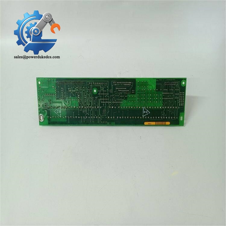
GE 531X305NTBAJG1
Quality Control Process
- Incoming InspectionVerify part number labels, serial traceability and PCB appearance. Check for circuit corrosion, scratch or disassembly traces.
- ESD ControlAll testing and storage work is performed on anti-static benches with anti-static wristbands.
- Bench Functional Live TestInstall board on matching GE DC300 test rack. Test relay contact continuity, serial communication, encoder interface and all analog signal channels. Continuous 24-hour aging test.
- Electrical Parameter TestingCheck auxiliary power output stability, insulation resistance of signal circuits.
- Final QC & PackagingGenerate formal test report, seal PCB with anti-static bag, wrap with bubble film. Attach QC passed label before shipment. Test photos and videos can be provided upon client request.
Module Replacement Pitfall Guide
- Lost Jumper Configuration RecordsRisk: Encoder no signal, wrong communication voltage, drive unable to close speed loop.Advice: Take clear photos of all jumpers before removal. Do not rely on memory.Real case: A maintenance engineer skipped recording jumper settings. It took one full shift to troubleshoot encoder communication failure after board replacement.
- Skip Analog Potentiometer CalibrationRisk: Analog speed feedback deviation leads to unstable drive speed and vibration.Advice: Record original potentiometer positions, readjust after installation and verify feedback values.
- Ignore ESD ProtectionRisk: Static discharge damages delicate onboard signal circuits, triggering intermittent random faults.Advice: Wear anti-static wristbands for all PCB handling, especially in dry environments.
- Confuse Similar NTBA Model SuffixesRisk: Install mismatched revision board, terminal signal mapping disorder.Advice: Confirm full complete part number printed on PCB silkscreen, do not judge only by prefix 531X305NTBA.
- Neglect Ribbon Cable Connection CheckRisk: Poor contact causes sporadic signal dropout.Advice: Inspect ribbon cable pins for bending or oxidation before locking the connector.



 Start Chat


