

Description
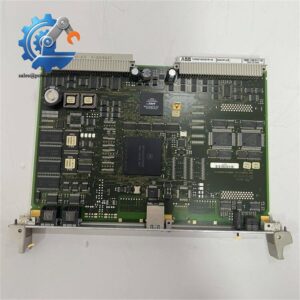
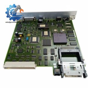
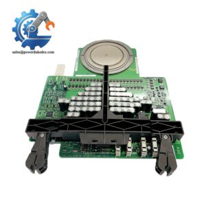
- GE DS200SHVMG1AGE | Genuine OEM DS200 Series Turbine Control Spare Circuit Board
Product Core Brief
- Model: DS200SHVMG1AGE
- Brand: GE General Electric (GE Vernova)
- Series: Speedtronic Mark V DS200 Turbine Control Platform
- Core Function: High voltage signal conditioning and isolation interface for M-Frame SCR excitation drives
- Type: SHVM High Voltage M-Frame Interface Board
- Key Specs: Shunt signal conversion (-500 ~ +500 mV) | VCO frequency output 0–500 kHz | Configurable onboard jumpers
- Condition Note: New Surplus, non-refurbished
⚠️ Mark V DS200 hardware is legacy platform. OEM delivery lead times are extended, global spare stock is limited.
Key Technical Specifications
| Parameter | Details |
|---|---|
| Full Part Number | DS200SHVMG1AGE |
| Functional Name | SHVM High Voltage M-Frame SCR Interface Board |
| Compatible Equipment | Mark V M-Frame SCR Exciter, DC2000 / AC2000 Drive Assembly |
| Signal Conversion | Converts -500 mV ~ +500 mV shunt analog signal to 0–500 kHz differential frequency signal |
| Core Circuit | Onboard VCO (Voltage Controlled Oscillator) circuits |
| Configuration | 17 configurable jumper positions for drive attenuation setup |
| Interfaced Partners | DCFB / SDCI power supply board, PCCA power connect card, LDCC communication board |
| PCB Protection | Conformal coated circuit board for anti-humidity and anti-corrosion |
| Operating Temperature | -20 °C ~ +65 °C |
| Relative Humidity | 5% ~ 95% RH, non-condensing |
| Mechanical Form | Standard plug-in PCB for Mark V control cabinet |
| Installation Environment | Indoor control cabinet, IP20 |
| Reference Manual | GEI-100174 |
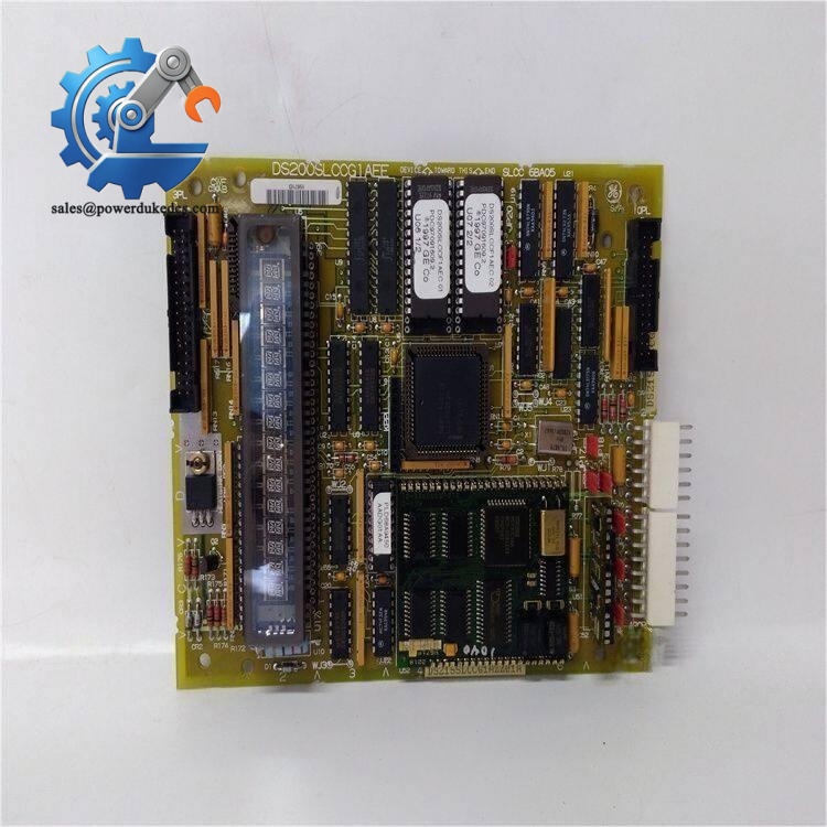
GE DS200SHVMG1AGE
Product Introduction
Application Scenarios & Pain Points
- Combined Cycle Power Plants – Gas Turbine Mark V Excitation Cabinets
Process SCR bridge feedback signals to stabilize generator excitation voltage under varying load conditions.
- Thermal Power Plants – Steam Turbine Generator Exciter Control
Real-time monitoring of excitation DC current to support voltage regulation and reactive power control.
- Oil & Gas Facilities – Gas Turbine Driven Compressor Generator Sets
Ensure stable power supply for compression units under variable process load.
- Cogeneration Plants – Waste Heat Turbine Generator Control
Sustain continuous excitation feedback for long-cycle unattended operation.
- Industrial Power Stations – Independent Turbine Generator Excitation Systems
Match different capacity exciters via adjustable onboard jumper settings.
Last quarter, a 300MW combined-cycle power plant captured continuous excitation feedback fault alarms on its Mark V rack. After troubleshooting, engineers confirmed DS200SHVMG1AGE signal conversion failure.
Official GE lead time reached 10 weeks. Operating the generator without reliable excitation feedback violated site safety operating rules.
Our stocked DS200SHVMG1AGE completed full bench testing and shipped within 3 working days. Maintenance technicians finished replacement during planned shutdown, duplicated original jumper configuration. Excitation current feedback returned stable after power-on commissioning. The site added two identical boards to critical spare inventory afterwards.
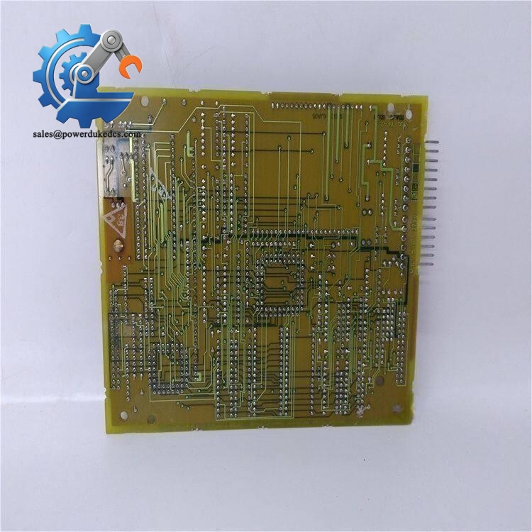
GE DS200SHVMG1AGE
Compatibility & Replacement Matrix
DS200SHVMG1AGE → DS200SHVMG1A / DS200SHVMG1AG : Pin compatible hardware, but different revision artwork; jumper layout differs, not plug-and-play.
DS200SHVMG1AGE → Mark VI / Mark VIe series boards: Different system architecture, fully incompatible.
⚠️ Important reminder: Photograph every jumper position on the faulty board before disassembly. Incorrect jumper configuration leads to excitation regulation drift or protection tripping.
Quality Control Procedure (Transparent Testing Standard)
- Incoming Inspection
Serial number and nameplate verification. Visual inspection for PCB scratches, corrosion, disassembly traces and connector damage. Check conformal coating integrity.
- Bench Functional Live Test
Test platform: Complete Mark V simulation rack equipped with LDCC, DCFB and exciter signal simulator.
Test items: Power-on initialization, shunt signal input simulation, VCO frequency output verification, continuous 24-hour ageing test. Formal test report available upon request.
- Electrical Parameter Test
Signal linearity test, insulation resistance test, continuity check for all jumpers and connectors.
- Hardware Archive
Record board hardware revision; photograph full jumper layout and component side for file storage.
- Final QC & Packaging
Inspector signature confirmation. Sealed inside anti-static bag, wrapped with bubble film and export carton. Attached QC Passed label with testing date. Testing photos or video can be provided to clients.
Field Installation Pitfall Guide
-
Jumper Configuration Mismatch
Common mistake: Install new board with factory default jumper settings. Excitation current feedback will deviate severely.
Advice: Take clear photos of all jumpers on faulty board before removal and replicate exactly.
Case I met: A power plant skipped jumper copying, spent one day debugging abnormal generator voltage fluctuation.
-
Ignoring High-Voltage Isolation Safety Rules
This board interfaces directly with SCR high voltage circuits. Improper wiring creates electric shock risks and board burnout.
Advice: Cut off all high-voltage power before board removal and installation.
-
Rough Insertion Damages PCB Traces
Mark V PCBs adopt fine printed circuits. Forced plug-in easily causes invisible open circuits.
Advice: Align backplane connectors gently; avoid applying heavy force during insertion.
-
ESD Damage Risk
Onboard oscillator and signal processing chips are sensitive to static electricity. Dry cabinet environments raise hidden failure risk.
Advice: Wear grounded ESD wrist strap during unpacking and installation.
-
Missing Excitation Parameter Verification
After board replacement, always verify excitation current feedback readings against actual field values.
Advice: Perform full load excitation test during commissioning to confirm closed-loop regulation performance.



 Start Chat


