

Description
- ABB COMMANDER 310 | Universal Input Controller Supporting Modbus RTU Communication
Product Core Brief
- Model: COMMANDER 310 (C310)
- Brand: ABB
- Series: Commander Instrumentation Range
- Core Function: Single-loop PID regulation for temperature, pressure and flow process control
- Type: Field-mounted universal process controller
- Key Specs: IP66 / NEMA4X housing; Built-in ramp/soak programs; Universal sensor input; Modbus RTU optional
Condition: New Surplus, non-refurbished
⚠️ ABB discontinued serial production since 2015; official successor model is CMF310, spare stock quantities are limited
Product Introduction
Key Technical Specifications
| Parameter | Specification |
|---|---|
| Model | COMMANDER 310 (C310) |
| Mounting Type | Wall mount / Pipe mount |
| Protection Rating | IP66, NEMA 4X |
| Control Algorithm | P, PI, PID, auto-tune, cascade, feedforward |
| Control Modes | Single output, Heat/Cool, Motorized valve control |
| Program Function | 9 profiles, maximum 30 ramp/soak segments |
| Input Types | Thermocouple, Pt100 RTD, DC mV, 0–10V, 4–20mA |
| Input Accuracy | 0.1% full scale |
| Communication Option | RS485 Modbus RTU, isolated interface |
| Display | Dual red 7-segment LED digital display |
| Ambient Operating Temp | -10 ℃ ~ +55 ℃ |
| Power Supply Options | 24 V DC / 100–240 V AC |
| Sensor Diagnostics | Broken sensor detection with configurable fail-safe action |
| Successor Model | ABB ControlMaster CMF310 |
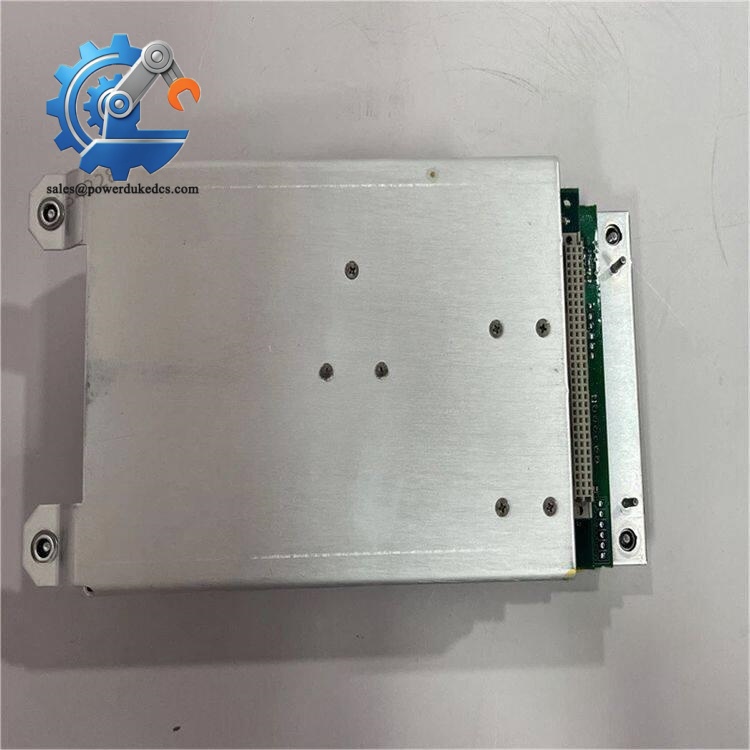
ABB COMMANDER 310
Installation & Configuration Guide
Phase 1: Pre-Installation (Estimated 15 min)
- Schedule process shutdown and perform lockout-tagout procedures
- Disconnect all sensor wiring and auxiliary power before removing the unit
- Avoid cable strain during wiring; comply with local EMC wiring standards
- Prevent liquid ingress to terminal compartment during installation
- PH1 cross screwdriver
- Fluke multimeter
- Mobile phone for recording original wiring and parameter settings
- Cable glands matching enclosure entry size
- Record all PID parameters, setpoints and ramp/soak program data
- Photograph terminal wiring layout for reference
- Confirm supply voltage matches controller hardware configuration
Phase 2: Old Unit Removal (Estimated 12 min)
- Cut off power supply and wait 2 minutes for circuit discharge
- Unscrew cable glands and disconnect all wiring terminals one by one
- Remove mounting bolts to release the controller from wall or pipe bracket
- Inspect terminal block for corrosion and water contamination
Phase 3: New Unit Installation (Estimated 18 min)
- Unpack the controller and check exterior for damage
- Fix the unit firmly on mounting bracket; reserve space for cable routing
- Route cables through bottom glands and tighten glands to maintain IP rating
- Reconnect wires strictly following photographed terminal layout
- Confirm sensor type matches hardware input configuration
[ ] All cable glands fully tightened
[ ] No loose wiring strands inside terminal compartment
[ ] Power circuit isolated from signal wiring
[ ] Mounting bracket fixed without vibration risks
Phase 4: Power-On & Commissioning (Estimated 28 min)
- Switch on auxiliary power and check LED display starts normally
- Access parameter menu and restore saved PID values
- Select correct sensor type and scale range for process variable input
- Configure alarm thresholds and fail-safe actions for sensor break
- Test ramp/soak program execution if profile control is required
- Run closed-loop auto-tune for optimized PID response
- Maintain continuous monitoring for over 30 minutes without abnormal alarms
- Incorrect temperature reading: Verify sensor type selection and wiring polarity
- Unstable control loop: Re-run auto-tune or adjust PID gain manually
- Modbus communication failure: Check station address, baud rate and bus termination resistor
Frequently Asked Questions (FAQ)
-
Can COMMANDER 310 be directly replaced by CMF310 without modification?
Hardware mounting dimensions and terminal definitions differ. Direct plug-and-play replacement is not supported. You need to adjust wiring and re-enter all control parameters. Field projects require site testing before formal commissioning.
-
Does the controller support hot swapping during operation?
Hot swap is not allowed. Power loss will terminate control output and trigger process shutdown. All replacement work must be completed during planned downtime.
-
Can ramp/soak programs be uploaded via communication cable?
Program parameters can be modified over Modbus RTU, but most operators prefer local front-panel editing for small production batches. No dedicated PC configuration software is mandatory.
-
What risks exist for units operating below 0 ℃ ambient temperature?
Units manufactured before June 2010 may face slight drift on 4–20 mA analog output under sub-zero conditions. Install heating insulation if the controller runs in cold environments.
-
Can this controller work with multiple temperature sensors at the same time?
Only one primary process variable input is used for PID loop. Additional inputs can be configured for remote setpoint or valve feedback signal. It cannot execute multi-loop control.
-
Is spare front panel display interchangeable between different C310 variants?
Physically compatible, but parameter access levels are tied to internal firmware. Mixing spare displays may trigger menu access restriction issues.
-
Warranty terms for stocked COMMANDER 310 units?
We provide 12-month warranty under standard industrial operating conditions. Damage caused by incorrect wiring, water ingress, overvoltage or mechanical impact voids warranty coverage.



 Start Chat


