

Description
Product Core Brief
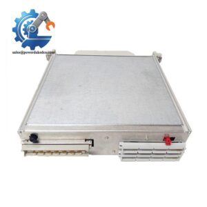
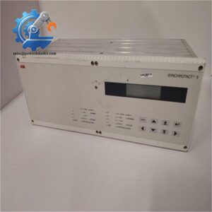
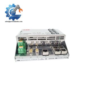
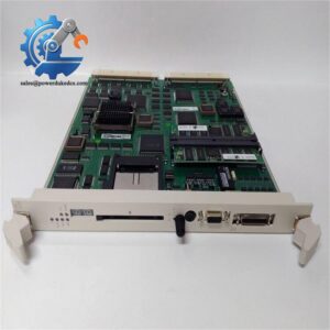
- Model: XO08R2
- Brand: ABB
- Part Code: 1SBP260109R1001
- Series: AC31 Series modular PLC system
- Core Function: Convert controller logic signals to relay contact outputs for field actuator control
- Type: Digital Relay Output Expansion Module
- Key Specs: 8 independent relay channels, 2 A continuous rating per channel, galvanic isolation
- Condition: New Surplus, non-refurbished
⚠️ Active production model, standard factory lead time applies, limited spot stock available
Product Introduction
Key Technical Specifications
| Parameter | Specification |
|---|---|
| Full Order Code | XO08R2 / 1SBP260109R1001 |
| Module Category | Digital Relay Output Extension |
| Output Channels | 8 independent normally open relay outputs |
| Rated Contact Load | 2 A / 250 V AC per channel |
| Logic Supply Voltage | 24 V DC |
| Isolation | Galvanic isolation between logic side and field contacts |
| Status Indication | Individual LED for each output channel |
| Mounting Method | Standard 35 mm DIN rail |
| Operating Temperature | 0 °C ~ +55 °C |
| Storage Temperature | -40 °C ~ +75 °C |
| Dimensions (W × H × D) | 96 mm × 32 mm × 80 mm |
| Net Weight | Approx. 120 g |
| Compatible Platforms | ABB AC31 Modular PLC controllers |
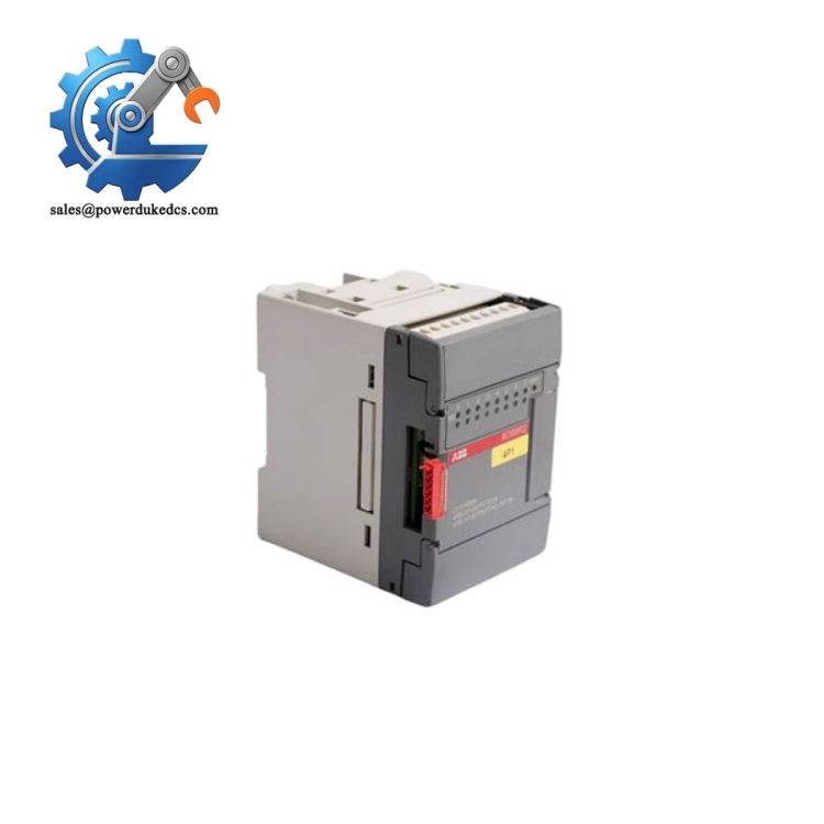
ABB XO08R2 1SBP260109R1001
Installation & Configuration Guide
Pre-Installation (Estimated: 10 min)
- Schedule maintenance window and execute lockout-tagout procedures
- Disconnect 24 V DC control supply before module modification
- Confirm all external field loads are de-energised
- Capture photos of existing module layout and wiring reference
- ESD wrist strap and anti-static work surface
- PH0 cross-head screwdriver
- Digital multimeter
- Mobile camera for recording wiring layout
- Export controller application program and save locally
- Note existing I/O address mapping for subsequent project adjustment
Old Unit Removal (Estimated: 12 min)
- Label each field wiring terminal clearly before disconnection
- Unscrew terminal screws and separate all external cables
- Unlock the side bus connector between adjacent AC31 modules
- Push down the DIN rail retaining clip and slide the module outward
- Inspect terminal blocks for oxidation or overheating traces
New Module Installation (Estimated: 15 min)
- Wear ESD protection while unpacking the XO08R2
- Verify printed part number matches required spare
- Slide module onto DIN rail until the bottom clip locks firmly
- Push side bus connector to establish communication with main controller
- Reconnect field wiring following labelled terminal sequence
- Complete pre-power checklist:
☑ DIN rail lock fully engaged
☑ Side bus interlock properly connected
☑ All terminal screws tightened
☑ No loose strands inside terminal housing
Power-On & Function Test (Estimated: 25 min)
- Measure 24 V DC supply voltage within allowed tolerance
- Confirm no short circuits on external output wiring
- Restore control power supply; keep field loads disconnected initially
- Download updated project with newly assigned output addresses
- Force each output channel ON and verify corresponding LED activates
- Reconnect field loads and carry out full functional sequence test
- Run continuous monitoring for minimum 30 minutes to detect abnormal heating
- No channel LED response: Check bus interlock and project I/O configuration
- Relay clicks but load fails to operate: Verify external power supply for field devices
- Random channel faults: Inspect for loose wiring or inductive load back EMF
Frequently Asked Questions (FAQ)
A: Yes. This expansion unit connects to any AC31 main CPU or existing expansion modules via the built-in side bus. Maintain the original module sequence when replacing units.
A: Hot removal is not recommended. Live disconnection of the side bus can trigger controller faults or corrupt running logic. Always cut the 24 V control supply first.
A: Inductive loads generate voltage spikes during switch-off. Fit freewheeling diodes or RC suppressors across coils to extend relay service life. Without suppression, relay contact wear accelerates rapidly.
A: Sum total current must stay below the 2 A per-channel continuous rating. Track inrush current at switch-on to avoid contact welding.
A: Address mapping depends on physical module position on the rail. If installed in a new position, update variable addresses inside the controller project and re-download logic.
A: ABB has not announced discontinuation. When sourcing alternatives, confirm bus protocol and channel quantity; many newer series modules cannot be directly swapped without program changes.
A: Warranty excludes damage caused by overload current, surge voltage, incorrect wiring, moisture ingress, or operation beyond published temperature limits. Every unit undergoes bench testing before dispatch; test documentation can be supplied on request.




 Start Chat


