

Description
- COEN ISCAN DSF-2000-MB-UV 2653-213-06 | DSP Flame Scanner with Automatic Self-Check Function
Product Core Brief
- Model: DSF-2000-MB-UV 2653-213-06
- Brand: COEN ISCAN
- Series: DSF-2000 Flame Scanner Series
- Core Function: Detect flame presence via UV spectrum and transmit status to control systems
- Type: UV Flame Scanner / Flame Detector
- Key Specs: RS485 Modbus RTU, built-in periodic self-test, adjustable flame detection sensitivity Condition: New Surplus, non-refurbished ⚠️ Original manufacturer end-of-life model, limited available inventory
Product Introduction
Unnoticed flame loss inside boilers or furnaces creates severe explosion risks. The COEN ISCAN DSF-2000-MB-UV 2653-213-06 is a compact UV flame scanner built for continuous combustion safety monitoring. It captures ultraviolet radiation emitted by flames and uses on-board DSP circuits to filter interference from hot refractory surfaces and ambient lighting.
Standard DSF-2000-UV versions only provide dry contact signals. This MB variant adds Modbus RTU over RS485, enabling digital data transmission to PLC and DCS platforms. Continuous site operation records confirm stable performance within -40°C ~ +70°C, widely adopted on gas-fired boilers, process heaters and industrial furnaces in power and petrochemical facilities.
Key Technical Specifications
| Parameter | Specification |
|---|---|
| Full Part Number | DSF-2000-MB-UV 2653-213-06 |
| Device Type | UV Spectrum Flame Scanner |
| Detection Spectrum | Ultraviolet UV band |
| Communication Interface | RS485 Modbus RTU (MB version exclusive) |
| Power Supply | 24 V DC ±10% |
| Response Time | <100 ms for flame loss detection |
| Self-Test Cycle | Automatic self-check every 20 seconds |
| Operating Temperature | -40 °C ~ +70 °C |
| Enclosure Rating | IP65 housing |
| Mounting Method | Threaded flange mounting for burner sight ports |
| Output Options | Digital Modbus data + relay flame status contact |
| Feature | EASI electronic aiming assist for field alignment |
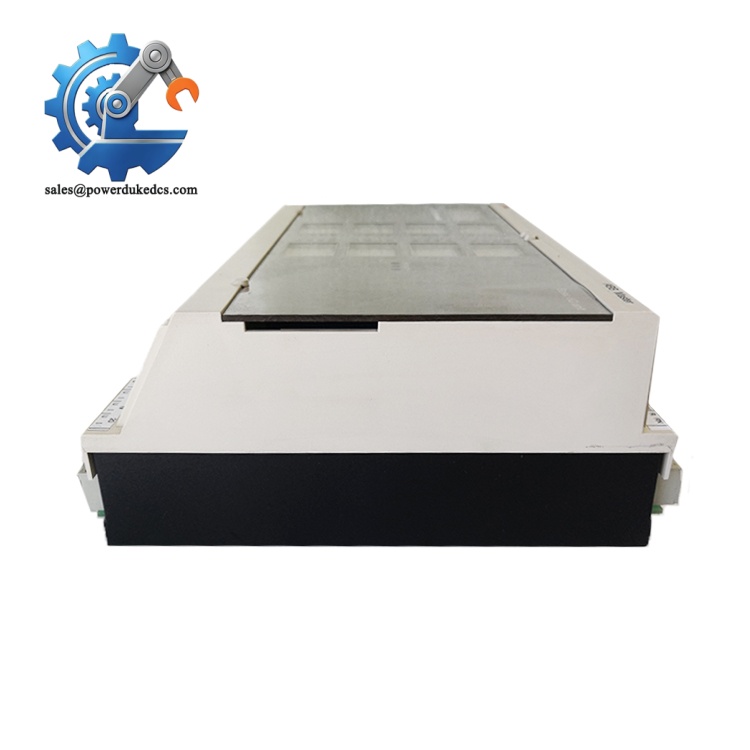
COEN ISCAN DSF-2000-MB-UV 2653-213-06
Installation & Configuration Guide
Pre-Installation (Estimated 10 minutes)
⚠️ Safety Reminders
- Arrange planned shutdown of the burner system. Do not install while the furnace is hot.
- Isolate scanner 24 VDC power and lock out power circuits.
- Confirm furnace temperature drops to safe ambient level before field work.
Tools to prepare:
- PH1 screwdriver
- Digital multimeter
- Mobile phone for recording wiring and mounting angle
- Thread sealant for sight port mounting thread
- Label tape for communication cables
Preparation tasks: Document existing scanner mounting angle. Record Modbus station address, baud rate and parity settings for later configuration.
Removal of Old Scanner (Estimated 12 minutes)
- Confirm power supply to the flame scanner is fully cut off.
- Disconnect power wires and RS485 communication cables one by one, mark each conductor clearly.
- Unscrew the scanner flange from the burner sight port. Rotate slowly to avoid thread damage.
- Clean residual carbon deposits inside the sight tube. Carbon buildup blocks UV light and causes false faults.
- Inspect sight port sealing gaskets; replace worn gaskets to prevent hot gas leakage.
New Scanner Installation (Estimated 16 minutes)
- Apply thread sealant evenly on scanner mounting threads. Do not over-tighten the flange.
- Install the scanner into the sight port, adjust viewing angle according to reference photos. Target the main flame zone.
- Connect 24 VDC power and RS485 A/B communication cables strictly following wiring diagram.
- Use EASI aiming assist function to fine-tune position until stable flame signal is displayed.
- Secure cable gland and confirm no loose wiring near hot furnace surfaces.
Pre-power-on checklist: [ ] Scanner firmly mounted without loose threads [ ] Power and RS485 wiring polarity correct [ ] Sight tube free of carbon contamination [ ] Cable routing avoids direct contact with high-temperature surfaces
Power-On & Functional Testing (Estimated 30 minutes)
- Restore 24 VDC power to the scanner. Observe status LED for normal initialization.
- Connect Modbus configuration tool, set matching station address, baud rate and parity.
- Start burner ignition sequence. Verify scanner detects flame immediately after ignition.
- Cut off fuel supply to trigger flame loss; confirm scanner sends flame absent signal within 100 ms.
- Maintain burner steady operation for minimum 30 minutes. Monitor Modbus flame signal continuously, check for intermittent dropout.
- Write mounting parameters and test results into equipment maintenance log.
Troubleshooting hints:
- No flame detection: Check sight port carbon contamination or incorrect aiming angle
- Modbus communication failure: Verify A/B wire sequence and bus termination resistor
- Frequent false flame faults: Reduce detection sensitivity or clean optical window
Frequently Asked Questions (FAQ)
- Can I hot-swap the DSF-2000-MB-UV scanner while the burner keeps running? Not recommended. Temporary loss of flame signal will trigger burner safety shutdown. Always schedule a burner stop for replacement.
- What is the difference between DSF-2000-UV and DSF-2000-MB-UV? The base DSF-2000-UV only provides relay contact outputs. The MB model integrates RS485 Modbus RTU, supporting digital flame strength data and fault code uploading to control systems. They are not direct plug-and-play interchangeable without program modification.
- Does this scanner support multi-fuel burners (natural gas and fuel oil)? Yes. UV detection principle works for gas and light oil flames. Heavy fuel oil may produce soot covering the optical window, increasing maintenance frequency.
- How long is the warranty for this surplus flame scanner? Every unit completes optical detection and Modbus communication bench testing before shipment. We offer a 12-month functional warranty. Test records can be provided upon request.
- Can multiple DSF-2000-MB-UV devices run on one RS485 bus? Yes. Each scanner requires an independent Modbus station address. Do not assign duplicate addresses on the same bus segment.
- What typical failure signs appear on a faulty DSF-2000-MB-UV? Common symptoms include periodic flame loss alarms, inability to establish Modbus connection, failure to pass automatic self-test, and weak flame signal readings even with stable combustion.
- How often should the optical window be cleaned during routine maintenance? For gas-fired boilers, inspect and clean the lens every 3 months. For oil-fired heaters, shorten the interval to 4–6 weeks. Carbon accumulation is the top cause of scanner misoperation.



 Start Chat


