

Description
- Emerson P188.R2 | ESD Protected Signal Allocation Module for Oil & Gas Automation Equipment
Product Core Brief
- Model: P188.R2
- Brand: Emerson
- Series: Industrial Rack Signal Interface Board Series
- Core Function: Route and distribute analog and digital signals between main controller and field instruments
- Type: Signal Allocation Circuit Board
- Key Specs: Multi-pin edge connector; ESD protection circuit; -20 °C ~ +70 °C operating range Condition: New Surplus, not refurbished ⚠️ This PCB assembly has reached OEM end-of-production, available inventory quantity is limited.
Product Introduction
Unstable signal wiring and improper signal splitting frequently trigger intermittent measurement alarms in process control cabinets. The Emerson P188.R2 works as intermediate signal routing hardware inside control racks to standardize field wiring layout.
This printed circuit board establishes fixed signal distribution paths, eliminating messy splice wiring inside cabinets. It carries built-in surge and electrostatic protection to reduce interference induced by long field cables. The board matches standard rack slot dimensions, designed for fast swap-out during planned maintenance. Field technicians rely on this board to simplify wiring troubleshooting and shorten equipment downtime in refinery and gas metering stations.
Key Technical Specifications
| Parameter | Details |
|---|---|
| Full Part Number | P188.R2 |
| Manufacturer | Emerson |
| Hardware Type | Signal Allocation Interface PCB Assembly |
| Operating Supply | 24 V DC |
| Operating Temperature | -20 °C ~ +70 °C |
| Electromagnetic Compliance | IEC 61000 EMC standards |
| Connector Form | Multi-pin edge backplane connector, external terminal header |
| Protection Features | Onboard ESD and transient surge protection circuits |
| Installation Method | Standard rack slot mounting |
| Supported Signal Types | Analog input, digital discrete I/O, low-speed communication signals |
| Application Scenarios | Gas flow metering systems, oil & gas remote control cabinets, process automation skids |
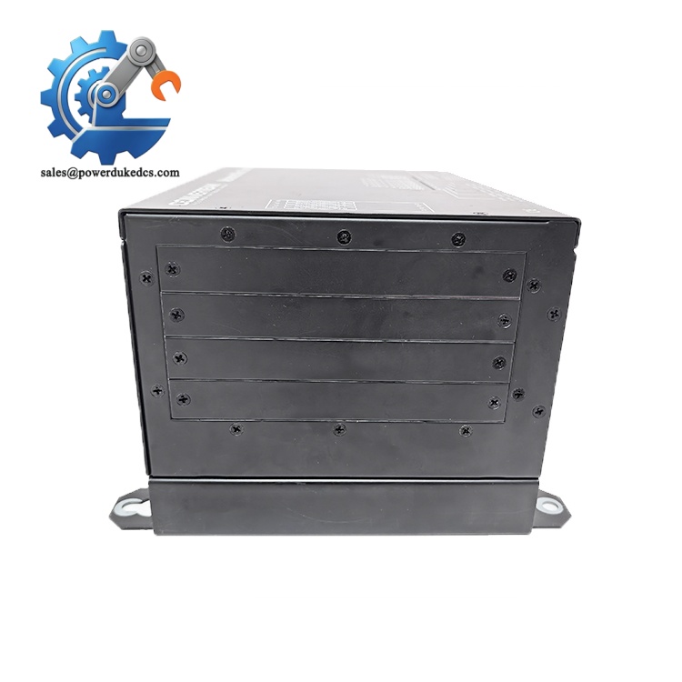
Emerson P188.R2
Installation & Configuration Guide
Phase 1: Pre-Installation (Estimated: 10 minutes)
⚠️ Safety Reminders
- Coordinate operation staff to lock relevant control loops before maintenance.
- Schedule planned shutdown; hot removal will disconnect all related field signals.
- Prepare ESD protection to avoid static damage to PCB traces and chips.
Tools to prepare
- Anti-static wrist strap and anti-static work mat
- PH1 cross screwdriver
- Digital multimeter
- Mobile phone for capturing wiring and connector photos
- Label tape for marking each signal wire
Backup work
- Take clear photos of all front-side and back-side wiring terminals of existing board.
- Record all wire number mappings for fast recovery after replacement.
Phase 2: Remove Old P188.R2 Board (Estimated: 11 minutes)
- Confirm cabinet power supply is fully disconnected. Wait 5 minutes for capacitor discharge.
- Unplug external terminal cables one by one, mark every wire according to photos.
- Loosen fixing screws on the board front panel.
- Pull the board straight outward horizontally; avoid twisting to prevent bending backplane pins.
- Inspect backplane connector pins for corrosion, dust or bending. Clean contacts with dry compressed air if needed.
⚠️ Do not yank cables forcefully. Damaged signal wiring causes unstable measurement after replacement.
Phase 3: Install New Circuit Board (Estimated: 16 minutes)
- Wear anti-static wrist strap before removing the board from anti-static packaging.
- Double-check part number to confirm P188.R2 matches replacement requirements.
- Align the board with rack guides, push evenly until the backplane connector fully seats.
- Tighten front fixing screws evenly, avoid over-tightening which may deform PCB.
- Restore all field wiring strictly following labeled photos.
Self-check checklist [ ] Part number verified completely [ ] All signal wires connected to corresponding terminals [ ] Board sits level inside rack without tilt [ ] No loose wiring terminals
Phase 4: Power-On & Functional Test (Estimated: 24 minutes)
Pre-power inspection
- Measure cabinet 24 V DC supply voltage to exclude overvoltage risk.
- Check no short circuit between power and signal terminals.
Power-on steps
- Restore cabinet power, keep field equipment under safe status temporarily.
- Observe system controller status; confirm no immediate signal fault alarms pop up.
- Navigate control software to check analog signal values and digital status feedback.
- Trigger several field device status changes to verify signal transmission direction.
- Maintain continuous running for over 30 minutes, monitor for intermittent signal drift.
Troubleshooting hints
- No signal reading: Check backplane connector seating and wire terminal tightness.
- Fluctuating analog values: Check shielding wiring and separate signal cables from high-power AC lines.
- Persistent channel fault: Recheck wire assignment mapping against original records.
Frequently Asked Questions (FAQ)
- Can I hot-swap the Emerson P188.R2 without cutting cabinet power? Hot swap is not supported. Pulling the board out will disconnect all field signals on related channels, likely triggering process interlock trips. Only perform replacement during scheduled equipment shutdown.
- Is P188.R2 compatible with other Emerson rack interface boards? This board follows dedicated signal routing definitions. Direct substitution with other PCB models will cause signal mapping errors. Confirm the original part number before purchasing.
- What testing procedures do you execute before shipment? Every unit undergoes visual inspection, continuity testing and power-on aging test. We can provide test screenshots on request; short testing video can also be arranged for customer verification. All stock items carry a 12-month warranty.
- Can this board handle high-frequency pulse signals from flow meters? It supports low-speed pulse signals. For high-frequency turbine meter pulse input, use dedicated pulse acquisition modules instead for better signal integrity.
- How long will delivery take for available inventory? Stock stored in Xiamen warehouse can ship within 1–3 working days. If stock is exhausted, we can arrange last-time sourcing; confirmed lead time will be notified before formal order confirmation.
- What are typical failure modes of aging P188.R2 boards? Intermittent signal loss, unstable analog readings and open-circuit channels are common faults. Most failures stem from connector oxidation or internal circuit component aging under long-term cabinet temperature cycling.



 Start Chat


