

Description
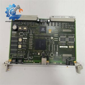
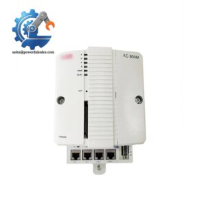
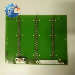
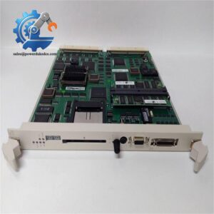
- ALSTOM V0701596-001102 | Direct Replacement Field Signal Input Unit
- V0701596-001102 | Industrial Grade Digital I/O Module for Power Automation
Product Core Brief
- Model: V0701596-001102
- Brand: ALSTOM
- Series: ALSTOM Legacy Power & Industrial Control Platform
- Core Function: Collect binary field switch signals and transmit status data to rack controller
- Type: Digital Input Module
- Key Specs: Optocoupler isolation, standard rack plug-in design, channel fault indication
- Condition: New Surplus, non-refurbished, no disassembly or component replacement traces
- Status: ⚠️ Factory discontinued, limited remaining inventory
Product Introduction
Unstable binary signal sampling creates blind spots for protection and monitoring loops inside power plant control racks. The ALSTOM V0701596-001102 acts as the front-end signal collector for legacy ALSTOM automation systems. It acquires contact status from circuit breakers, isolators and local field sensors.
Built with independent opto-isolation for each channel, this module blocks external electrical interference and prevents surge damage spreading into the main control rack. Many thermal power and hydroelectric facilities still rely on this hardware for retrofitting old control systems. Steady channel sampling suppresses signal bounce during frequent equipment switching.
Key Technical Specifications
| Parameter Item | Technical Value |
|---|---|
| Full Part Number | V0701596-001102 |
| Applicable Platform | ALSTOM legacy rack-based control system |
| Signal Type | Binary digital input |
| Isolation Mode | Channel-wise optocoupler isolation |
| Operating Supply | 24V DC rack internal power |
| Mounting Standard | Standard plug-in metal chassis rack installation |
| Indicator Layout | Individual channel LED status lamp, common fault LED |
| Operating Temperature | -20 °C ~ +60 °C |
| Protection Class | IP20 for cabinet installation |
| Net Weight | 0.51 kg |
| Typical Application | Thermal power plant, hydropower station control cabinet |
| Origin | Europe |
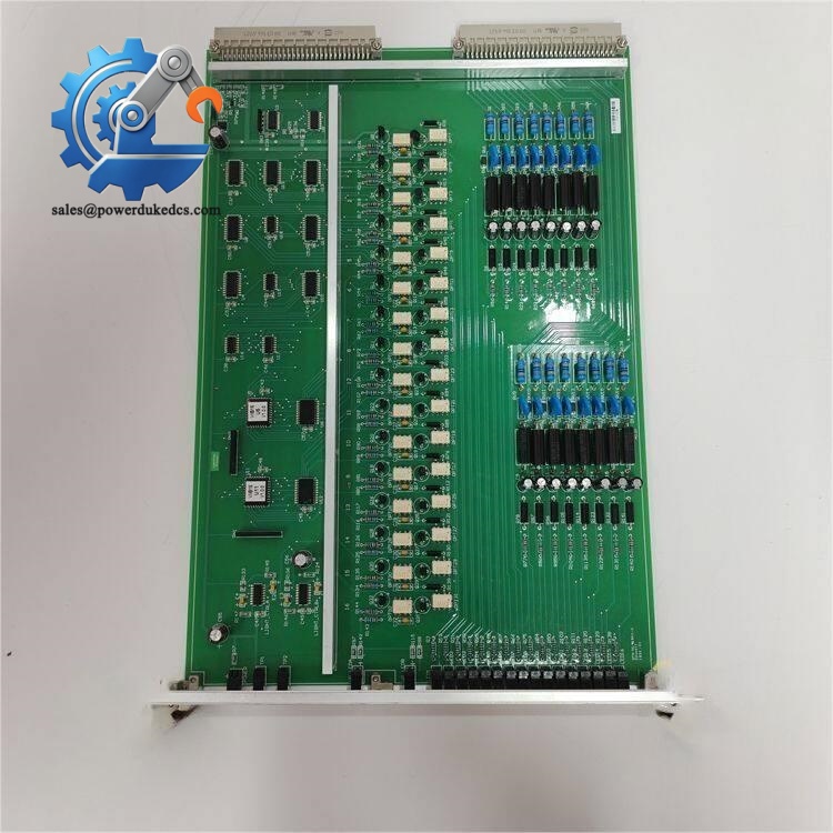
ALSTOM V0701596-001102
Installation & Configuration Guide
Stage 1: Pre-Installation Preparation (10 mins)
⚠️ Safety operations take priority for all rack module replacement. Notify maintenance staff of planned downtime. Switch related protection logic to safe mode. Cut off rack main power and UPS power supply. Keep power disconnected for at least 5 minutes to discharge internal capacitors.
Prepare standard tools: anti-static wristband and anti-static mat, PH1 cross screwdriver, digital multimeter, marking labels, mobile phone for configuration backup. Complete backup tasks: export controller project configuration. Take clear photos of wiring terminal layout, hardware jumper positions and overall rack slot arrangement.
Stage 2: Old Module Removal (9 mins)
Release the front panel fixing latches. Label every field signal cable terminal number to avoid mismatching during reinstallation. Loosen terminal screws counterclockwise and pull cables out gently.
Release the rack locking mechanism and slide the module horizontally outward. Separate the circuit board from the backplane connector slowly. Inspect backplane pins for bending or dust accumulation. Clean debris with dry compressed air if needed. Keep all handwritten configuration labels attached to the original module before removal. Do not twist the mainboard during disassembly.
Stage 3: New Module Installation (11 mins)
Wear anti-static equipment before opening anti-static packaging. Confirm full model V0701596-001102 matches your replacement demand. Replicate jumper and address settings strictly according to saved photos. Incorrect hardware address settings easily trigger bus communication conflicts across the whole rack. Align the module with rack guide grooves, push horizontally into position until the lock mechanism clicks. Reconnect all labeled field cables and fasten terminal screws with moderate torque.
Pre-power-on self-check checklist:
- Hardware address jumpers match site configuration
- All signal cables securely connected
- Module fully locked inside rack slot
- No loose tools left within control cabinet
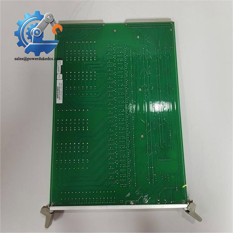
ALSTOM V0701596-001102
Stage 4: Power-On & Functional Testing (13 mins)
Use multimeter to verify 24V DC supply voltage stays within rated range and confirm no short circuit between power and ground terminals. Power up the control rack alone first. Observe front panel LEDs: lit channel lamps indicate normal signal detection; constant red fault light points to wiring short or hardware abnormality.
Connect ALSTOM official configuration software to scan rack network nodes. Confirm the new module can be identified on the backplane bus. Load backed-up control configuration and activate online mode. Manually trigger several field binary signals and check real-time status feedback on HMI. Maintain continuous operation for over 30 minutes without persistent alarms. Record module serial number and replacement time into maintenance archives.
Common troubleshooting tips: Module undetected on bus usually comes from wrong station address; repeated channel alarms often relate to field wiring short circuit or polarity reversal.
Strict Quality Inspection SOP
All stocked ALSTOM V0701596-001102 modules complete full testing workflow before shipment to eliminate hidden operational risks for industrial spare parts users. 1. Warehouse Incoming Inspection We verify serial number authenticity and original label integrity. Conduct comprehensive visual inspection to check circuit corrosion, surface scratches, solder repair traces and component aging. All hardware version marks are filed for reference.
2. Live Rack Functional Test Modules run testing on our ALSTOM legacy control test rack. Test procedures cover power-on self-test, backplane bus handshake and full-channel signal simulation. We record operating data over continuous 24-hour load test and issue independent test reports for each unit.
3. Electrical Performance Testing Fluke measuring instruments perform insulation resistance and continuity tests. All electrical indicators must comply with official hardware specifications. Units with abnormal circuit characteristics get rejected directly.
4. Hardware Configuration Documentation Record factory default jumper and address settings. Photos are stored as files to support customers for on-site configuration reference.
5. Final QC & Packaging Professional inspectors confirm all test items pass. Modules are sealed inside anti-static bags, wrapped with bubble film and packed into cartons. Each package attaches a QC Passed sticker with inspection date. Test photos or short videos can be provided upon customer request.
Field Pitfall Avoidance Guide
Years of on-site maintenance work prove most replacement failures arise from trivial operational errors rather than module quality defects.
1. Skipping jumper replication before disassembly Factory default hardware address settings rarely match existing site control systems. Many technicians power on directly after installation without adjustment, which may crash rack-wide communication. We handled one hydropower station case where incorrect jumpers caused 4 hours of protection system offline. Always photograph original jumper layout before removing the old module. Never rely on memory for configuration.
2. Ignoring ESD protection measures Signal sampling circuits contain sensitive semiconductor chips. Static discharge in dry seasons can damage internal circuits without visible traces. We witnessed a case where a brand-new module failed immediately after power-on because the engineer skipped anti-static wristband. Anti-static protection must be implemented every time.
3. Rough insertion damaging backplane pins Forced skewed insertion bends backplane connector pins and leads to unstable signal contact. Even with anti-reverse structure on the rack, misaligned pushing can still create permanent hardware damage. Keep the module horizontal during plug-in operation.
4. Confusing input channel polarity Each binary input channel has defined positive and negative terminals. Reverse wiring leads to permanent signal loss, even if no hardware alarm appears. Cross-check official wiring diagrams instead of judging by experience.
5. Compatibility risk of EOL hardware Well, technically this model stops original production. Some updated ALSTOM system software revisions have limited adaptability to older hardware variants. Confirm your existing controller software version before placing orders.
Following these reminders helps avoid over 90% of on-site rework and unexpected downtime.
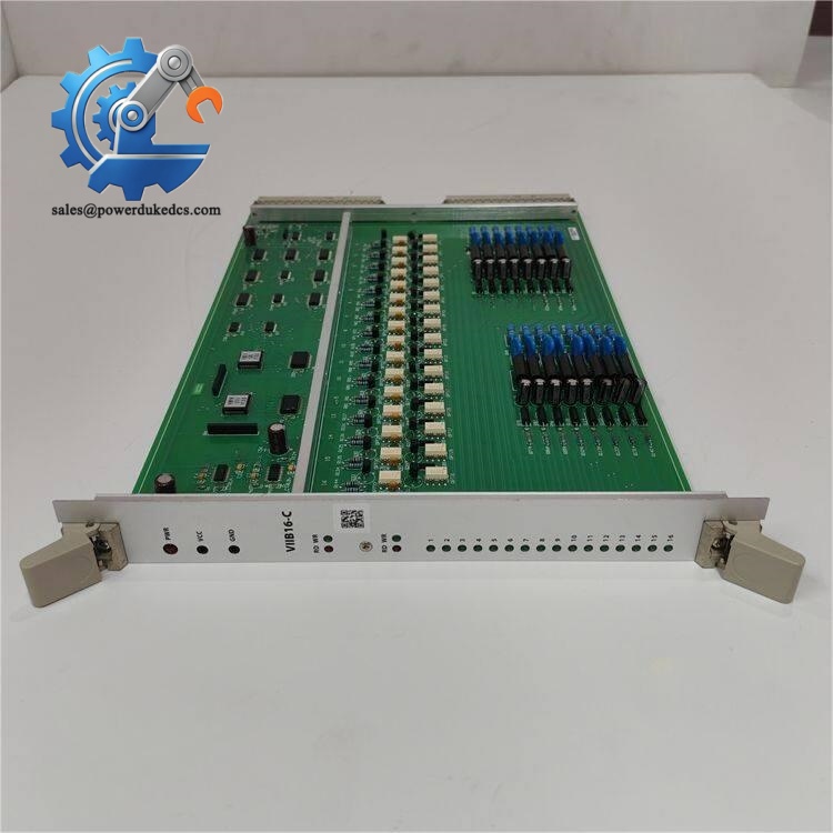
ALSTOM V0701596-001102
Frequently Asked Questions (FAQ)
1. Does ALSTOM V0701596-001102 support hot swap? Hot swap cannot be performed under normal running status. Live removal interrupts rack bus communication and triggers protection system alarms. Full power-off and capacitor discharge are mandatory before replacement.
2. Is this board interchangeable with similar ALSTOM digital input variants? Different suffix versions carry slight differences in channel logic and bus protocol. Physical dimensions may match, but you still need to confirm hardware revision and system software adaptation to avoid communication faults.
3. Do I need to flash extra firmware after installation? Basic digital sampling functions use solidified onboard firmware; no additional flashing required. You only need to set hardware station address and download system configuration after mounting.
4. What causes steady red fault LED illumination? Constant red fault light generally comes from three typical causes: wrong bus address, field channel short circuit, or internal circuit hardware failure. You can isolate faults step by step by disconnecting external wiring first.
5. What after-sales support can be offered? All stocked modules carry a 12-month warranty. We supply complete test reports, remote technical guidance during installation and troubleshooting. Listed prices act only as reference; reasonable negotiation is available for bulk inquiries.
6. Why select original surplus module instead of generic substitutes? Third-party replacement boards cannot fully match the signal sampling timing and bus protocol of legacy ALSTOM control systems. For power plant protection loops, mismatched signal processing may introduce hidden safety risks. Original spare parts prevent unpredictable adaptation failures.



 Start Chat


