

Description
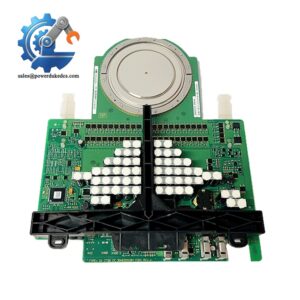
- GE DS200DCFBG1BJB | Genuine GE DS200 Series Turbine Control Circuit Board
Product Core Brief
- Model: DS200DCFBG1BJB
- Brand: General Electric (GE)
- Series: DS200 / Mark V Speedtronic Turbine Control
- Core Function: DC feedback & control power board, supplies regulated DC power and processes drive feedback signals
- Type: DCFB (DC Feedback) Power Circuit Board
- Key Specs: ±24VDC / +5VDC Output | Configurable Jumpers & DIP Switches | Built-in Fuse Protection
- Condition: New Surplus, non-refurbished
⚠️ This board is officially discontinued by GE; worldwide available inventory is limited.
Key Technical Specifications
| Parameter | Specification |
|---|---|
| Full Part Number | DS200DCFBG1BJB |
| Functional Name | DC Feedback Board (DCFB) |
| Input Voltage | 115 VAC / 230 VAC jumper selectable, 50/60 Hz |
| DC Outputs | +24 VDC, -24 VDC, +5 VDC control power |
| Auxiliary Output | 115 VAC for cabinet cooling fans |
| Configuration Hardware | 7 sets of DIP switches, 12 configurable jumpers |
| Protection | Independent fuses for input and each DC output circuit |
| Diagnostic | Status LED indicators, accessible test points for signal verification |
| Operating Temperature | -40 °C ~ +70 °C |
| Supported Platforms | Mark V Speedtronic, AC2000, DC2000, EX2000, FC2000, ME2000 drives |
| Reference Document | GEI-100028 |
| PCB Coating | Standard conformal coating for industrial environments |
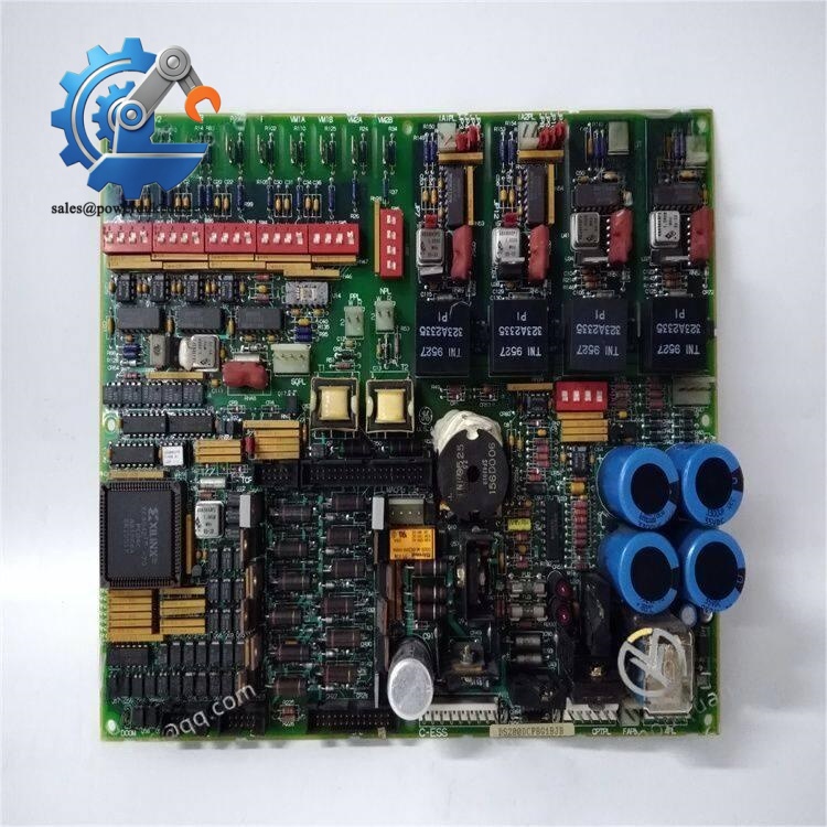
GE DS200DCFBG1BJB
Product Introduction
Application Scenarios & Pain Points
- Thermal Power Plants – Steam Turbine Excitation Control
Supply control power and monitor excitation feedback for turbine generator EX2000 excitation systems.
- Oil & Gas – Gas Turbine Cogeneration Units
Support Mark V control racks for pipeline compression gas turbines and distributed power generation turbines.
- Heavy Industry – Large Variable Speed DC Drives
Deployed on DC2000 / AC2000 drive cabinets for large motor control in steel, mining and chemical plants.
- Refineries – Process Gas Compressor Turbines
Maintain stable drive closed-loop control under continuous variable load operating conditions.
A coastal thermal power plant operated two 300MW steam turbine units equipped with Mark V control systems. One DS200DCFBG1BJB suffered capacitor aging failure during peak load. The turbine tripped offline automatically. GE official supply channel required 14 weeks delivery.
The maintenance team sourced spare DS200DCFBG1BJB unit. We completed full power-on testing and recorded all factory default jumpers. After delivery, technicians copied original jumper and DIP settings, finished replacement within the planned maintenance window and avoided a second unplanned outage. This event pushed the site to stock two DCFB spare boards permanently.
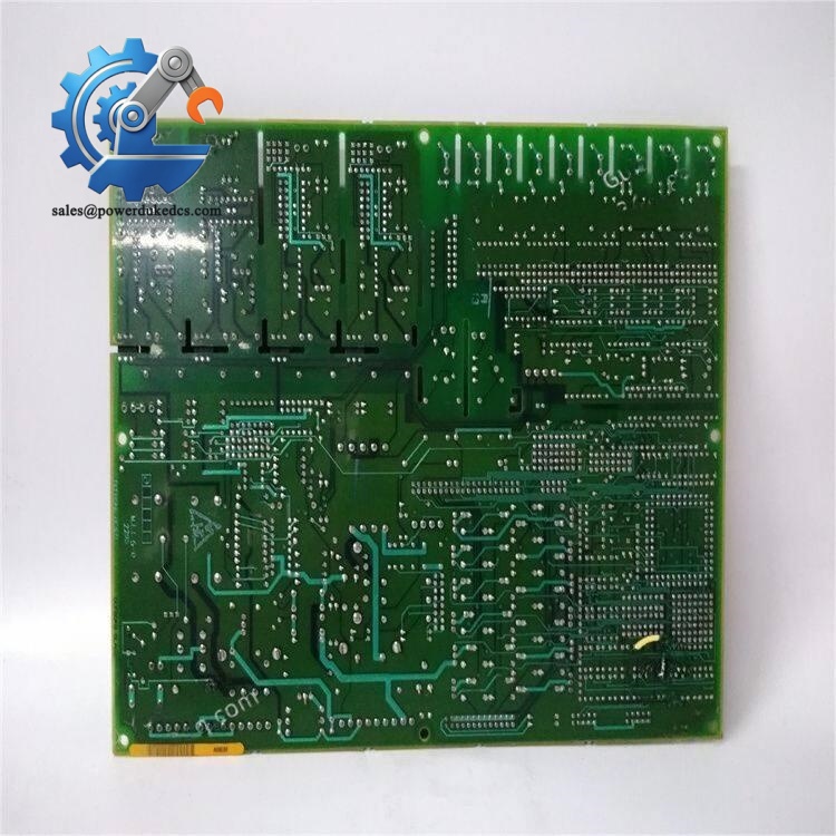
GE DS200DCFBG1BJB
Compatibility & Replacement Matrix
DS200DCFBG1BJB → DS200DCFBG1BKC : Limited compatibility; Some hardware component revisions differ, bench test strongly recommended before site installation
DS200DCFBG1BJB → Generic non-GE power supply boards : Not compatible; Unique feedback signal processing circuit cannot be substituted
DS200DCFBG1BJB → Mark VIe series boards : Not compatible, different rack architecture and signal standards
Critical Replacement Notes
- Take clear photos of all DIP switch positions and jumper arrangements before removing the faulty board. Settings cannot be restored without records.
- Perform continuity and voltage testing after installation; mismatched jumper configuration will trigger drive overvoltage or turbine trip alarms.
- Confirm cabinet input AC voltage matches board jumper selection (115VAC or 230VAC). Wrong selection will destroy onboard power circuits.
- Check all fuse status after power-up; record LED diagnostic status for future troubleshooting.
Quality Control Testing Process
- Incoming Inspection
Serial number verification, full visual PCB inspection, check capacitor bulging, solder joint conditions, scratches and repair traces.
- Power-on Live Bench Test
Install on compatible Mark V test rack, conduct continuous 24-hour burn-in test. Verify all DC output voltage levels, LED diagnostic operation and fuse alarm simulation.
- Electrical Parameter Test
Measure all output voltage stability, insulation resistance test, verify feedback signal conversion function via test points.
- Hardware Configuration Record
Document DIP switch layout and available jumper positions; save complete test logs.
- Final Packaging
Anti-static sealed packaging with shock-resistant bubble wrap. Test photos and inspection reports available upon request.
Field Installation Pitfall Guide
-
Lost Jumper & DIP Switch Configuration
I met a site case where maintenance engineers removed the faulty DCFB board without taking photos. After installing the spare unit, the drive kept tripping. Three days were spent tracing circuit drawings to recover original settings. Photograph every configuration before disassembly.
-
Incorrect AC Input Jumper Setting
The board supports 115VAC and 230VAC input selection. If the jumper is set incorrectly, the primary power circuit will burn immediately after power application.
-
Ignoring Conformal Coating & Contamination
Many old control rooms have dust and humidity. After board replacement, check ventilation; accumulated dust leads to partial discharge and short-circuit failures on coated PCB surfaces.
-
Skipping ESD Protection
Signal processing circuits on DCFB boards are sensitive to static electricity. Wear anti-static wristbands at all times during handling. Static damage may not appear until weeks after installation.
-
Overlooking Fan Power Circuit
This board supplies 115VAC to cabinet cooling fans. If fan circuits short-circuit, internal fuses blow and cut off all control power. Check fan wiring before powering up the new board.



 Start Chat


